Tracing Journal: Nordland ODR-C Custom Overdrive
The gear community is not known for restraint when hyping cool pedals. But you don’t have to be part of the DIY pedal scene for long before you start to understand that very few of the drive-of-the-day pedals have the substance to back it up. Any of us can list off a half-dozen circuits that enjoyed a ride on the TGP hype train for a few weeks but turned out to be nothing more than a Tube Screamer or RAT once people looked under the hood.
So you can appreciate that it’s rare to see a pedal that is hyped as much as the Nordland ODR-C, and yet when you look under the hood and see how it’s made, it not only lives up to the hype but manages to exceed it.
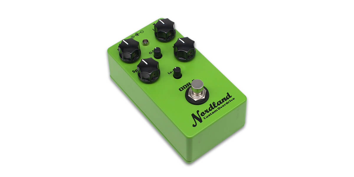
The ODR-C is an updated version of the Nobels ODR-1 Natural Overdrive, designed by Kai Tachibana as an original circuit for Nobels that first released in 1992. Intended as a low-budget alternative to the Tube Screamer, the ODR-1’s build quality was less than great, but to those who played it, it was undeniable that the circuit itself was something special. It steadily increased in popularity over the following decades until today when it’s often found in lists of the top 10 overdrives of all time.
In 2019, Kai decided to revisit the ODR-1 and update it with a few new features under his own Nordland brand name. The result is the ODR-C Custom Overdrive, a brilliantly-designed handmade pedal that occupies the opposite end of the spectrum from the ODR-1 in both build quality and price. It features three new controls: a low cut that fixes the bass-forward tone of the original, a midrange control that can boost or cut, and an “overdrive de-compress” (ODC) control that gradually adds higher-threshold clipping diodes in the soft-clipping stage. Each of the three knobs can be set to a position that emulates the original ODR-1, so the core circuit remains the same despite all the added features.
The Andromeda, based on the ODR-1, has consistently been one of our most popular projects and kits. So it was hard to resist tearing into an ODR-C and seeing what improvements could be made after 27 years.
Tracing photos
We actually took apart two of these. The first unit was a 2019 model, among the first that were made, and it’s mostly through-hole with a few SMD parts (the JFET and two MOSFETs).
Through-hole version


SMD version
The second one was a new 2021 version which is hybrid SMD, using several through-hole film capacitors but SMD resistors and active components. Since it was newer, this is the one that we dissected for the main trace. As with most SMD traces, it did not survive, but it lived a good life and died in service to the DIY community. (The through-hole version above was used to confirm the trace, removing it from the enclosure to check part values visually, but we kept it away from the soldering iron and it will live on for many years.)


")

")

")


")
As you can see, both versions display incredible craftsmanship. It uses a double-decker “sandwich” PCB form factor (similar to Xotic pedals and our Hypercube and Blueshift) to make the most of the available space and keep the pedal compact. There are a few custom 3D-printed braces and jigs to hold everything in place, keeping the battery and LED trimmer easily accessible while the rest of the circuit is protected. Everything is precise and not a millimeter is wasted. (Check out the video from Nordland showing the assembly process in more detail.)
Schematic
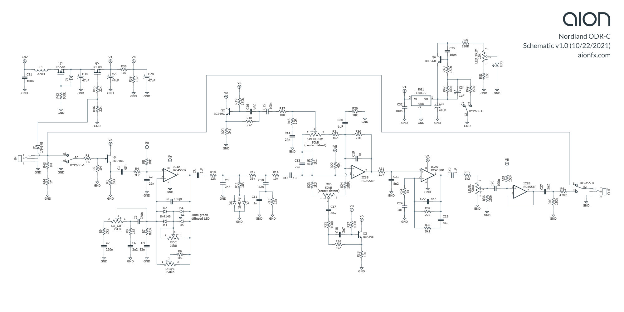
Note that the component numbering does not follow the original unit. The potentiometer sub-PCB reuses some of the numbering from the main board, and so a complete schematic of the whole unit with the original numbering would have some duplicate references.
Analysis
As expected, the the ODR-C is faithful to original ODR-1. But, while the end result should sound pretty much identical to the original, there’s a pretty long list of changes.
Changes from ODR-1
- The minimum drive resistor (R6) has been moved in between pins 2 and 3 of the drive pot instead of being in series with the pot. The value has also been changed from 1k8 to 1k2. This alters the taper of the drive knob and lowers the minimum drive very slightly.
- C3 has been changed from 120pF to 150pF, which will make the stage cut slightly more treble, but it wouldn’t even be measurable until higher drive settings.
- A few 10R resistors have been added: one in series with the hard-clipping diodes (R11), and two in the Spectrum section (R16/17) for better isolation between the lowpass and gyrator. These have zero impact on the tone, more just theoretical engineering optimizations.
- C8 and C25 (coupling capacitors) have been reduced from 2.2uF to 1uF and changed from electrolytic to film. Since they’re both coming straight from the output of an opamp stage which is very low-impedance, 1uF will perform the same, but the quality and longevity are much higher since they are now film capacitors.
- C12 has been added, a 1uF coupling capacitor between the hard clipping and the tone controls. Another engineering optimization that doesn’t make any practical difference, but on paper it’s better for isolating the stages from each other.
- The tone control op-amp has been reconfigured slightly. In the ODR-1, the R29 gain-ratio resistor went to the bias voltage, but in the ODR-C it now goes to ground. A 1uF capacitor (C20) has been added to block DC, required when bias voltage is used instead of ground, but it’s made large enough so that no bass is cut (rolloff at 16 Hz). Additionally, R30 has been changed from 20k to 22k, and C19 has been changed from 560pF to 1n. This raises the gain of this stage very slightly and cuts a little more treble. It’s possible these changes was made to compensate for the addition of the Mid control and related circuitry to keep the overall response the same as the original.
- The Spectrum potentiometer value has been increased from 30k to 50k, likely because 30k is a non-standard value, and it now has a center detent so it’s easy to find the 12:00 position.
- A 1k2 resistor (R35) has been added in series with the Level control, reducing the maximum volume very slightly.
- A tapering resistor (R36) has been added between lugs 1 and 2 of the Level control. This was likely done in conjunction with R35 so that the volume knob met some desired performance standard, e.g. unity at 12:00.
- The capacitor after the Level control has been changed to 100n. In the original unit, this is the point where the JFET switching occurs, and when the unit is engaged, there are two 1uF capacitors in series for an effective value of 500n. 100n is still large enough to pass the full bass frequency, so no real difference here either.
- The output capacitor (C27) has been lowered from 3.3uF to 2.2uF and changed from electrolytic to film. Again, no real impact on the bass frequencies since it’s coupling a low-impedance source, but the quality is better.
- A 470R resistor (R41) has been added in series with the output. This is commonly seen in similar pedals from BOSS and Ibanez, and again it’s just a good-practice change with no practical impact.
- The bias voltage divider has been changed from 15k/15k to 10k/13k. This shifts the bias voltage slightly higher than half supply, and was likely changed in order to optimize the performance of the ICs. Many op-amps clip asymmetrically at the rails and will benefit from a slightly off-center bias voltage so the clean headroom is maximized without increasing the supply.
New controls
The ODR-C features three new controls for a total of six knobs. Here’s what they do.
Low Cut
The original ODR-1 has an extraordinary amount of bass, so a low-cut control is essential to get the most out of it. When I released the original Andromeda project in 2015, it had the first implementation of a low-cut control to the ODR-1 circuit, so I was curious to see how close this knob this was to my solution.
The verdict: it’s similar in concept, but more flexible. The static R7-C4 filter (2.4kHz) is always present, but the Low Cut knob pans between the original R8-C6 filter (48 Hz) and a second R-C combo with a much higher rolloff of 329 Hz. In the middle, both R-C filters are equally “out” of the circuit and have little impact on the tone. Since these filters also impacts the gain ratio, the overall gain will be lower in the 12:00 position and will increase as you turn it left or right.
The ODR-C uses the same basic idea as the Andromeda, increasing the value of the filter resistor to reduce the intensity of the filter. But the ODR-C expands it in an inventive way by adding the second filter and changing the control into a blend that increases one filter as the other is reduced. So from 0 to 5, it’s almost identical to the Andromeda’s bass control, but from 5 to 10 it gradually shifts toward a low-mid EQ that the Andromeda (and the original ODR-1) can’t match.
One other thing to mention: there is a 220n capacitor (C5) positioned between the static 2.4kHz filter and the bass-heavy 48 Hz filter, and at first glance this may appear to be a backwards-incompatible departure from the original unit. But if you imagine the low-cut knob turned all the way to the left, pins 1 and 2 are shorted together, meaning C5 is completely out of the circuit. It only comes into play as the knob is turned to the right. At full clockwise rotation, the original R8-C6 filter is still connected, but C5 effectively reduces the bass-frequency capacitor to 200n, raising the filter frequency to 530 Hz.
This means that at full clockwise, there are three different filters in place at 329 Hz, 530 Hz, and 2.4kHz, each with slightly different levels of gain. At full counter-clockwise, the 530 Hz filter is shifted to 48 Hz, the 2.4kHz filter is still present, and the 329 Hz filter is effectively out of the circuit—meaning the gain-EQ structure of this stage is the same as the original ODR-1.
ODC (Overdrive De-Compress)
This one’s a bit more straightforward than the low cut, although I’ve never seen it implemented exactly like this. The soft-clipping feedback diodes each have an additional LED in series. The ODC potentiometer shorts out these LEDS on the minimum setting, effectively taking them out of the circuit. As it’s turned up, the LEDs are gradually blended in, which raises the clipping threshold so it’s more open and transparent.
However… it doesn’t seem like it would have a huge impact on the clipping character since the D6-D7 hard clipping diodes still clamp the signal at a fixed 0.7V regardless of whether the preceding signal is clipped low or clipped high. The edges of the clipped signal after D6/D7 would be a little harder since the signal going in is more dynamic, but overall the change would be pretty subtle.
Testing it seems to confirm this. There’s a difference across the rotation, but it’s not terribly drastic. It would likely do a much better job de-compressing if the D6/7 hard clippers weren’t there.
In fact, this might be an interesting modification: use a dual potentiometer for ODC, with the second half wired to add resistance in series with R11 and gradually fade out the hard clippers as the LEDs are faded in. It may need a parallel resistor to get a useful balance with the LED blender, but I bet there’s some potential there.
Either way, I’m interested to try the LED blender in a feedback diode circuit as an alternative to the typical 3-position toggle switch for diodes that I include in a lot of projects. It seems like it would cover the full range of the toggle switch but with added flexibility.
Mid Boost/Cut
The third knob is a little more textbook compared to the other two: a gyrator (simulated inductor) centered at 1073 Hz with a Q of 1.82. Topologically, it’s very close to the Spectrum control, but it operates at a different frequency, and it’s missing the Spectrum’s treble cut formed by C14 as well as the filters created by C13 and R15. It’s set up in a balance configuration where it cuts mids at the given frequency to the left and boosts to the right, with the 12:00 position being flat (reinforced by the center detent of the pot).
R23 and R24 shift the range of the pot slightly. Theoretically 50% rotation should be the flat point, but since the resistors on either end are different values, the detent does not correspond exactly to the 50% point.
Given the amount of detail in the rest of the design, it seems likely that this was done in order to make the center position as close as possible to the ODR-1, even if it meant that the gyrator was slightly off-center. It’s clear that the designer did a lot of frequency-response plotting during the development of the ODR-C, and sometimes things don’t work the same in the real world as they do on paper, so I would recommend trusting his advice here when he says the center detent is flat.
Polarity protection
The polarity protection and filtering is a little more complicated than you normally see. The inductor is used instead of the resistor that’s more commonly seen. Inductors often work better than resistors, plus they don’t drop the supply voltage at all. This is followed by Q4, a P-channel MOSFET that acts as a reverse-polarity protector similar to the one described by R.G. Keen in 1999. Again, almost zero voltage loss with this method, but P-channel MOSFETs can be harder to find so this method isn’t as practical as others. This is followed by Q5, which is connected to the ring of the input jack so that it only passes voltage if something is plugged in. This is downstream from the battery, so it acts as a more complex battery shutoff—the same effect as wiring the battery snap negative lead through the input jack ring, but with this method it also works on DC voltage.
LED dimmer circuit
This seems overly complex for what it does, but the designer clearly spent a lot of time on this portion of the circuit, so my suspicion is that he had a few other objectives in mind. Normally an LED dimmer would just be a trimmer placed in series with the current-limiting resistor for the LED. Here, the status LED is decoupled from the main power supply through a regulator and a PNP transistor that is used to turn it off and on. It also looks like there’s some pop suppression here—C34 should limit the current and turn on Q6 more slowly—so it’s likely an effort to keep the LED from injecting any noise into the audio path when it’s turned on and off.
Andromeda Deluxe
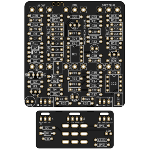 The Andromeda Deluxe is releasing today. It’s based on the audio path of the ODR-C, only cutting out the complex polarity protection and LED dimmer circuit.
This is perhaps the tightest layout I’ve ever done, but I did manage to get it all on one 125B-sized PCB with 1/4W resistors. I’m pretty proud of how it turned out. One or two more components and it would have been a different story.
Side by side, this will sound the same as the ODR-C. But we’ll reiterate that the original ODR-C is stunning piece of engineering and it’s worth every penny if you can afford one—not to mention supporting the talented designer of one of the best overdrive circuits ever made.