Skip to content

Straylight Chorus/Vibe

Based On
Univox Uni-Vibe
Effect Type
Chorus/phaser/vibrato
Build Difficulty
Advanced
Project Summary
Originally designed as a simulation of a Leslie spinning speaker cabinet, it uses an incandescent bulb and LDRs to produce an asymmetrical phase-shift effect. It was most famously used by Jimi Hendrix.

Complete Kit

What's included?
PCB, finished enclosure, hardware,
and all electronic components.
Out of stock

$139.00

Out of stock

Estimated availability: September 11, 2026
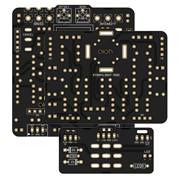
Straylight Chorus/Vibe printed circuit board

PCB Only

What's included?
Just the PCB. Build instructions and parts list can be viewed or downloaded from this page.

$16.00

In stock

In stock

Project overview

The Straylight Chorus/Vibe is an adaptation of the Univox Uni-Vibe, one of the earliest modulation effects originally released in 1967. It was most famously used by Jimi Hendrix, but it’s been used and adored by countless other professional musicians across its nearly sixty-year history.

The Uni-Vibe circuit is really a four-stage optical phaser as opposed to a true pitch-shifting vibrato, but aspects of the implementation (particularly the uneven capacitors in each stage) cause it to have a Doppler effect similar to a Leslie spinning speaker. The phase-shifted output can either be used on its own for vibrato or mixed with the dry signal for a chorus or phaser effect.

The Uni-Vibe uses a miniature incandescent lamp with four LDRs inside of a reflective box, and this is a key aspect of its sound. There have been many simplified versions of the circuit that use an LED or vactrols in place of the lamp and box, for example the Earthquaker Devices Depths and Danelectro® Chicken Salad, as well as the classic DIY EasyVibe by John Hollis. While they are excellent effects in their own right, they are all only approximations of the real thing.

The Straylight is identical to the original circuit from the 1960s with a few modernized conveniences. See below for details. If you want a more straightforward version of the Uni-Vibe that fits in a smaller enclosure and has a reduced set of features, check out the Straylight Mini.

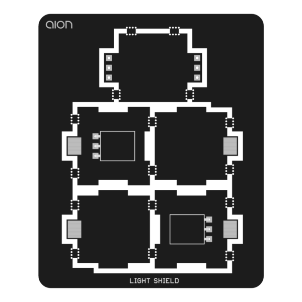
It’s recommended to also use our light shield, available separately, but you can cover the lamp and LDRs in several different ways. See build documentation for more information.

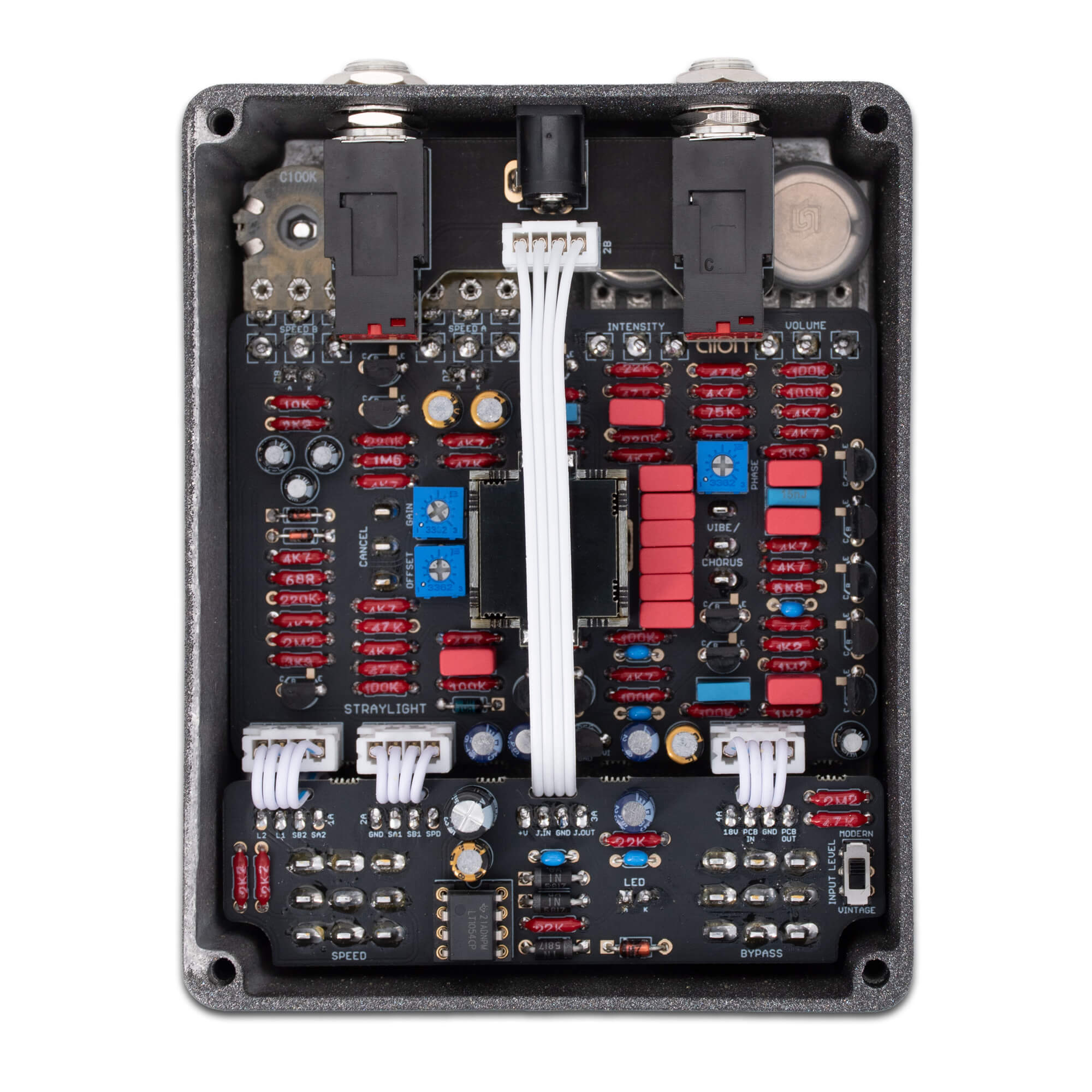
Straylight Chorus/Vibe Kit - InsideStraylight kit

The full kit includes everything you need to build the pedal shown in the photos above and to the right. All PCBs and parts are included in the kit, so you do not need to purchase the light shield separately.

If you’re building the kit, make sure to use the kit build documentation because the assembly methods are different.

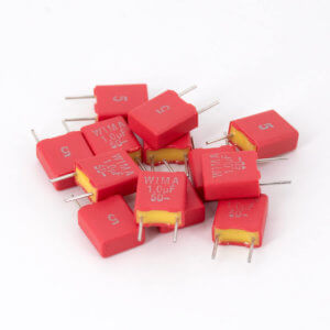
Note: The PCB-only version of this project uses a type of capacitor that has been temporarily discontinued by WIMA. Please see our news article about the issue and the substitution spreadsheet for project-specific recommendations. We are stocking a limited supply in the mean time. It does not impact the kits.

Circuit enhancements

The Straylight project is a direct clone of the original Uni-Vibe circuit, but with some added features and modernizations:

1. Charge pump: The Straylight uses a charge pump voltage doubler so that it can run off of a standard 9VDC supply instead of wall power like the original.

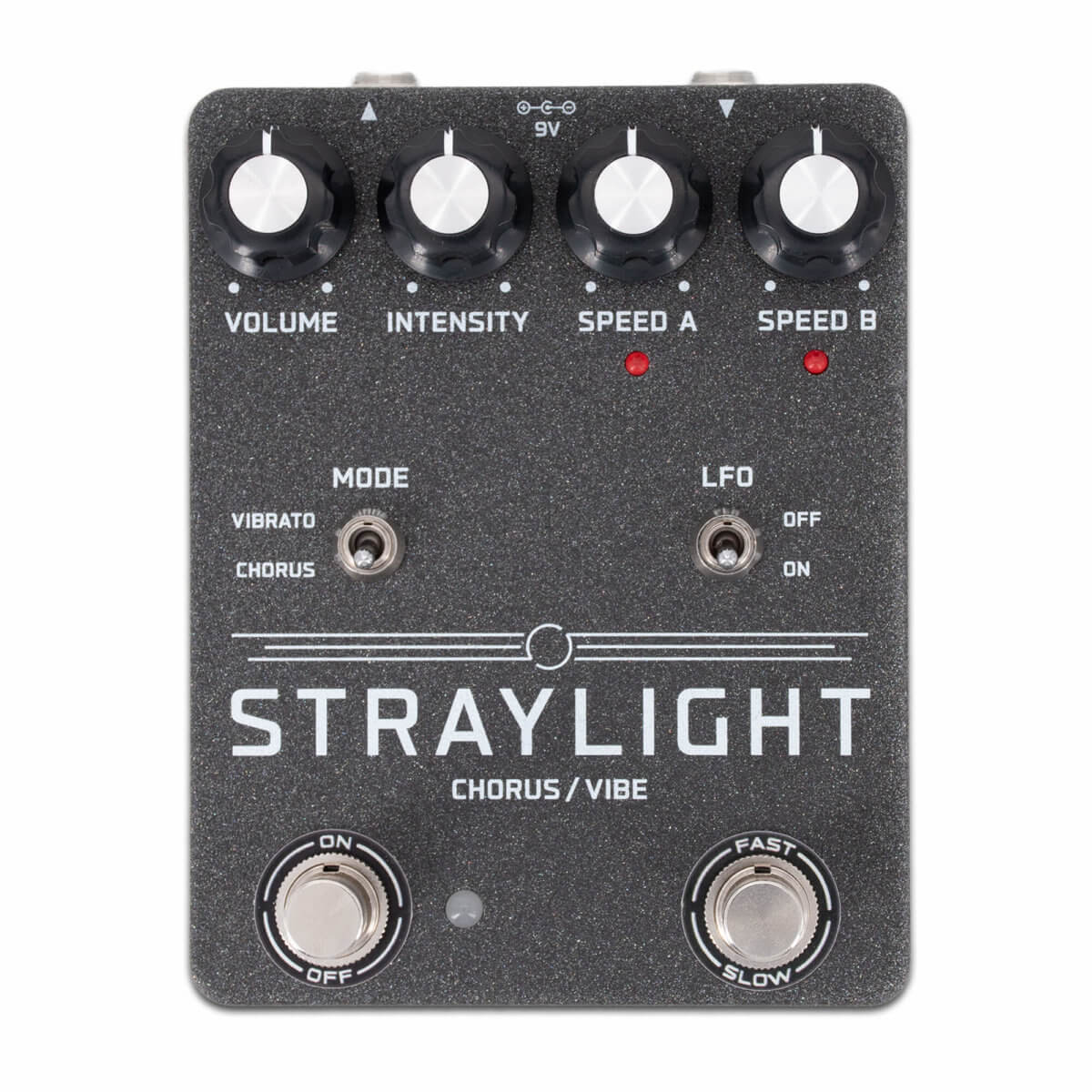
2. Dual Speed control: Like most clones, ours does not support a rocker pedal for the speed control, but we have added a second Speed pot on a footswitch so you can transition between two presets. If the two speeds are different enough, there’s a slight ramping effect when switching between them.

3. LFO Cancel switch: The original Uni-Vibe handled bypass mode by deactivating the LFO, so the signal still passes through the static phase-shift stages. This imparts a subtle coloration to the tone that many people like. So while standard true bypass is a better option all-around, we’ve included a toggle switch for Cancel mode so that this feature is still available.

4. Input level switch: The original unit had a significant volume drop at the input, cutting the signal by 1/3, which was responsible for the weak output. Some clones add an input buffer or boost stage to help with this. However, the issue is entirely caused by the 22k/47k resistors acting as a voltage divider. A much simpler solution is to just increase the value of the ground resistor to something much higher, such as 2.2M. But again, while this low impedance is a flaw in the circuit design, it’s grown to become part of the sound, so we’ve made both options available.