Tracing Journal: King Tone Octaland Mini
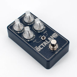
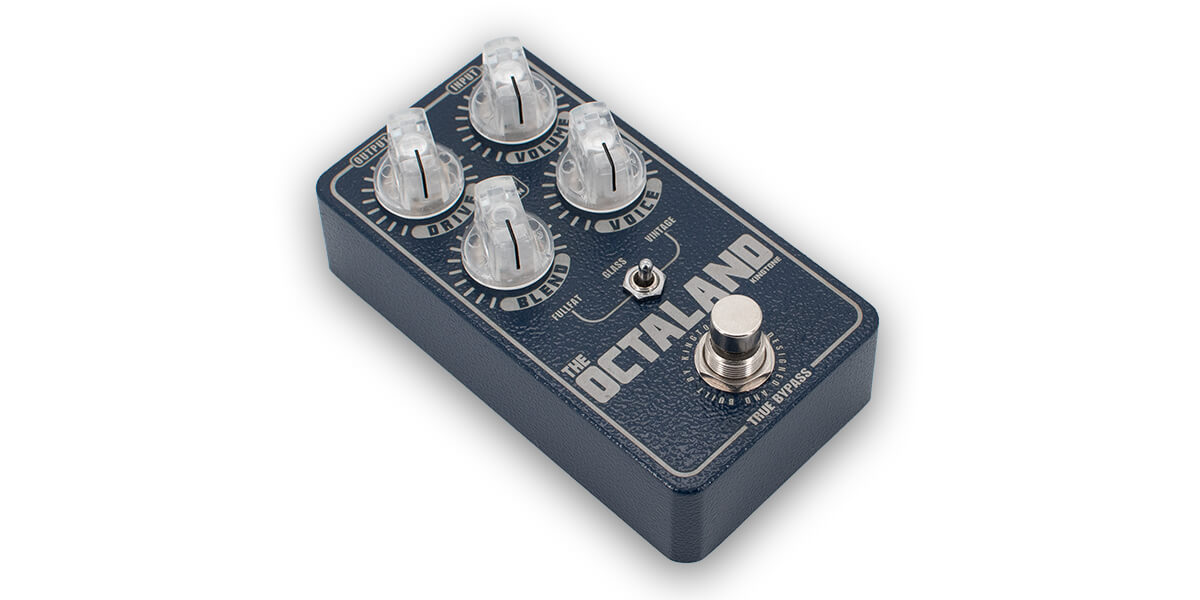
The King Tone Octaland Mini was originally released in 2019, an update to the big-box version from 2013 with added features. Here’s a demo video from Jesse Davey:
He’s pretty up-front about it being a hot-rodded Octavia, which brings to mind another trace of ours, the Catalinbread Octapussy. But the feature set as described—particularly the clean blend and tone control—would require enough extra circuitry that it had to be much more than a clone. We picked up blue-box unit from 2020, labeled version 1.2 on the PCB, and it did not disappoint!
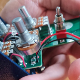
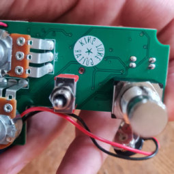
Tracing photos
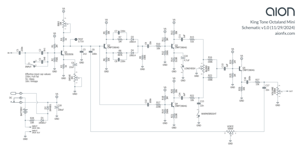
Schematic
Tracing notes
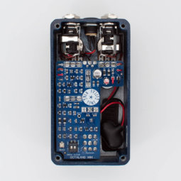
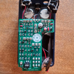
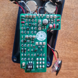
For this trace, we referenced two different Octaland Mini units. Both were blue enclosures, and both PCBs were labeled v1.2, but one PCB was green and the other was blue. There were no PCB differences and all component values were the same.
As you can see from the photos, we were able to do the trace without destroying either of the pedals, which is pretty uncommon. It helped that almost all of the values were printed on the PCB, although after the Blues Power trace, we approached this one with some distrust. If he intentionally mislabeled one or two values, it would be a great way to throw off tracers.
The resistors could be verified easily since they all have the codes printed on them. But SMD capacitors are unlabeled, and so we ended up removing all of them so they could be measured outside the circuit. Fortunately there was no misdirection in this case and they all checked out with the printed values. There were a few without labeled values: C-IN, C-WARM, C-VINT, TONE, and R-TONE (resistor). These measured the same in both units, so it’s likely the designations are just a byproduct of early experimentation before the values had been locked in.
The last thing to mention is that this is a 4-layer board. Only a small number of traces were on the inner layers, and it’s pretty easy to tell that the inner layers are used when you see a via that goes nowhere on the reverse of the board. So as long as you’re thorough with your multimeter and have a decent idea of the expected circuit topology, it’s not too hard to work out where everything goes.
Analysis
As expected, the main octave section is a close copy of the Roger Mayer Octavia (the transistor version, not the earlier transformer version). The input gain stage, where the Drive control is located, comes before the split into clean & octave paths. From there, a second nearly identical gain stage forms the clean path, while the adapted Octavia arrangement forms the octave path. These are blended together passively, then buffered before the output.
Switchable input capacitor
Using a combination of series and parallel capacitors, there are 3 different effective values for the input capacitor.
- With only C1 (220n) in the circuit and C2/C3 bypassed, we have “Full Fat” mode which passes the signal with almost no bass cut.
- When C1 is in series with C2 (5n1), the effective value is 5n, for “Glass” mode (least bass).
- When C1 is in series with C2, and C3 (5n6) is in parallel with C2, the effective value is 10.2n, for “Vintage” mode.
Dual-function tone control
The tone control is an odd value, 50kW. The basic idea is that it is reverse log taper from 0% to 50%, linear at 50% (in the sense that the 12:00 point is half the pot value), and then standard log taper from 50% to 100%. Here is a graph from GEOFEX showing how it compares to the other common tapers (the line labeled “5”):
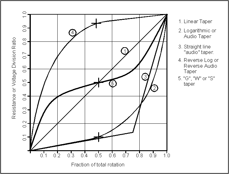
The most well-known application of a W-taper potentiometer is in in the tone control of the Tube Screamer (20kW).
In this application, it serves as a dual tone control, functioning as follows:
- At 0% (minimum rotation), C17 is grounded, giving a low-pass filter of 322 Hz at the very end of the circuit after the blend. C6 is in series with 50k of resistance to ground, which means it is effectively out of the circuit and only C5 is cutting any treble.
- At 100% (maximum rotation), C6 is grounded, cutting treble at the point where the signal is split between clean and octave paths. The low-pass frequency is a little more complicated since it depends on the output impedance of Q1, which is impacted by the bias trimmer and the gain control setting. But LTSpice simulation tells us that at stock bias and minimum gain, the corner frequency is around 290 Hz, and at maximum gain it’s shifted up to around 660 Hz. C17 is in series with 50k resistance to ground, so as with C6 in the other direction, it’s effectively out of the circuit.
- At 50%, it’s neutral. Both tone capacitors, C6 and C17, are nearly out of the circuit (25k series resistance to ground for each) for the least amount of treble cut in both sections of the circuit.
Often this type of dual-function control would use a dual pot so that the two sides of the circuit are fully isolated from each other. This use case is specific enough that it works well, with clear similarities to the BJFe Honey Bee’s Nature control. The difference between 25k resistance (center point) and 50k (0% or 100%) isn’t nothing, but the low-pass effect is perceived logarithmically, so it’s negligible.
DIP switches
Inside, there are two DIP switches to provide finer control over the tone.
- The Warm/Bright switch engages a 723 Hz low-pass filter on the clean path. (If that frequency seems familiar, once again it’s from the Tube Screamer, in this case the exact same center point of the mid-hump.) This filter is especially helpful on bass guitar, allowing the clean blend to restore the low-end without adding too much high-end to compete with the octave.
- The Low/High switch engages a 4.7uF emitter bypass capacitor on the octave gain stage, which increases the gain and low-end of the drive path significantly.
Note: An updated version of the Octaland was released in 2022 in a new style of enclosure. The controls are the same, but it has 6 DIP switches on the side. We have not seen inside one of these newer versions and don’t know what the new DIP switch settings correspond to in our schematic.
Bias trimmer
We do not know the exact procedure they used to set the bias. There is a pad labeled “TEST” that connects to the collector of Q1, and our unit measured 3.71V at this point. The trimmer was turned to around 45-47% rotation, just under 12:00.
Battery & power supply
The power section you see in the schematic is the third draft, the result of maybe an hour of probing around to try to figure out how the DC jack is wired. This was around the point where we lost interest. It didn’t match any conventions we’ve seen before, but since it was outside the main audio circuit and we standardize the power sections in all of our PCB adaptations, it was irrelevant for our purposes and we didn’t spend much time trying to make sense of it. As a result, it may not be entirely accurate and we are not claiming with any confidence that wiring of the power/battery section will work as shown.
We can confirm that between the diodes and the resistor, the positive supply loses around 0.3V in total. With a 9.6V supply, the main filter capacitor had 9.31V from positive to negative. The power supply resistor appears to be on the negative side of the supply rather than the positive, which means it won’t assist with filtering and will only help with current spikes. (Usually this resistor would be in series with the positive supply in order to form a stronger R-C filter with the main filter capacitor.)
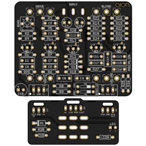 Ascalon Octave Fuzz
Releasing today is the Ascalon Octave Fuzz, our adaptation of the Octaland Mini. It’s the same circuit with no modifications or adjustments other than some additional power filtering and standardizing the battery wiring.
