Tracing Journal: Catalinbread Octapussy
The Catalinbread Octapussy was originally released in 2012. It was modeled after vintage transistor octave fuzzes like the Octavia. Here’s a demo:
They compare it to the Octavia but claim it’s an original design. There are only a couple of ways to get that octave-up fuzz tone in an all-analog topology, so we were skeptical. But regardless of the originality, it’s a fantastic-sounding octave fuzz that doesn’t sound quite like anything else out there.
Tracing photos


Schematic
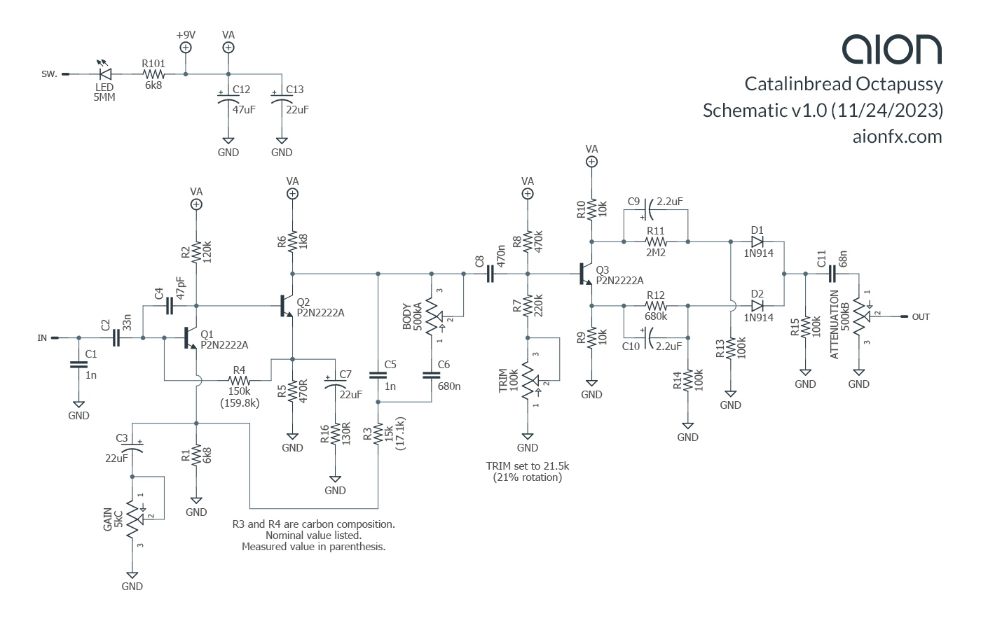
Analysis
The octave section is taken straight from a Roger Mayer Octavia with a couple of value swaps. No real surprises there. The front half of the circuit is the interesting part. It’s basically the gain stage of a Colorsound Overdriver, but the feedback loop by way of the R3 resistor has a pseudo-variable-capacitor added: a static 1n cap with a parallel 680n that can be faded out with the Body pot.
In the Overdriver, there is no capacitor, so it’s a full-frequency feedback loop. With the capacitors added, the gain is frequency-dependent. As the control is turned up, it reduces the effective capacitance from 681n to 1n, so it will only cut the gain on higher frequencies. This has the effect of adding low-end.
Curiously, the “Attenuation” control is nothing more than a reverse-wired volume control at the tail end of the circuit. Probably this is just a marketing decision to make it seem like it’s a more powerful pedal, since they recommend keeping it at zero (max volume) and only turning it up if it gets too loud. Traditionally, an attenuation control is an input volume, which in transistor fuzz circuits can completely change the feel of the effect in a different manner than the gain control, so by using this term it increases the likelihood of misunderstanding how it works.
Trimmer
The Octapussy has a trimmer that sets the base voltage of Q3. Assuming a 9.6V supply voltage, the trimmer has a range of 3.06V to 3.88V. We’re not sure what method Catalinbread used to set this trimmer, but in this unit it was set to 21.5k (21% rotation) which would result in a 3.26V base voltage.
Component types
If you check out the photos, particularly the last four, you’ll notice all types of components being used: carbon film and carbon comp resistors, and polyester, polypropylene, orange drop, electrolytic, and MLCC (ceramic) capacitors. The designer, Howard Gee, commented in the manual that these were all carefully chosen for their sonic properties and that it made a difference in their testing:
Another key parameter I worked is parts selection. I spent much time comparing the qualities of different types of capacitors and resistors in each position in the circuit and selected the types that gave the best possible tone and response. Many pedals are designed with no regard to the type of parts used, only considering the nominal value (e.g. 2.2uf or 1kOhm). It makes a difference! Sometimes subtle, sometimes epic! I don’t like to leave stones unturned so I investigate this area with every pedal I design in order to achieve the best sound and response I can.
In the original draft of this tracing journal, we started to break this apart, challenging the idea that the actual type of component had anything to do with the tone and that something else was going on that was a little more scientific—but this very quickly turned into its own article. If you want to read an in-depth discussion of the notion that these components sound different, check out Audio Qualities of Different Component Types.
Briefly, though, it’s almost certainly not the component types he was hearing, but the differences in actual value (i.e. resistance and capacitance) between the different component types.
Let’s look at the carbon comp resistors specifically as an example. We measured the two carbon comp resistors and found that the 15k resistor (R3) measured 17.1k, and the 150k resistor (R4) measured 159.8k. Both are 5% tolerance, but R3 is 14% above nominal and R4 is +6.5%. These resistors are each a part of their own feedback path for the input fuzz stage, responsible for both gain and EQ, so small differences here will have a much bigger impact than almost any other resistor position in the circuit.
At the low voltages of this pedal, the physical construction of the components won’t have any impact on perceived sonic characteristics—and certainly not anything that could be described as “epic”. But the resistance itself is more than enough to explain the difference in sound. For more discussion on this, check out the full article.
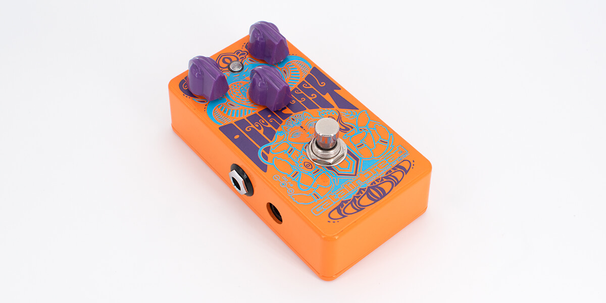
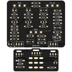 Nereus Octave Fuzz
Releasing today is our version of the Octapussy, called the Nereus. It’s a direct adaptation based on our trace. We did make one editorial change, which is to reverse the rotation of the attenuation control and make it into a standard volume control. There’s no practical reason to do it the way they did and it only creates unnecessary confusion.