The Hexatron Optical Phaser is an adaptation of the Mu-tron Phasor II, an LDR-based phaser originally released in 1977.
The Phasor II was originally designed as a simplified version of the Bi-Phase, a sprawling circuit that could be operated as a single 12-stage phaser or two independent six-stage phasers. The Phasor II is essentially one-half of a Bi-Phase, with a nearly identical LFO and phase-shift topology, but without the complex routing and LFO control options.
The Phasor II was the successor to the Phasor I, which was in production from 1974-1976. The Phasor I utilized CA3080 operational transconductance amplifiers (OTAs) which were relatively new technology at the time. This OTA phase topology predated the EHX Small Stone and was almost certainly the inspiration for both that circuit and the Maestro MP-1.
However, for the Bi-Phase and subsequently the Phasor II, they drew inspiration from the Uni-Vibe and replicated its LDR and lamp setup. They added two additional phase stages (six instead of four) and modernized the phase stages by using op-amps instead of transistors. They changed the incancescent lamp to an LED and redesigned the LFO to optimize the sweep for the new setup. By all accounts, it was a significant improvement, and it’s become legendary as one of the most organic, colorful, and vocal phaser effects ever made.
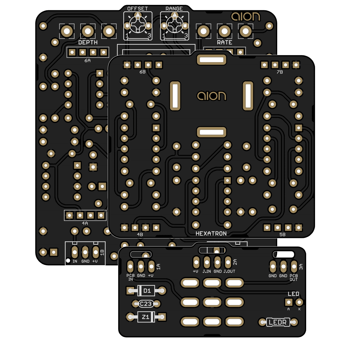
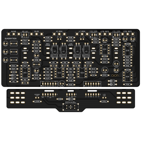
The Hexatron is a near-direct clone of the original Phasor II, but with a charge pump to get bipolar power from a standard 9V supply. Due to the size of the circuit, this project utilizes a stacked PCB layout in order to fit in a 125B enclosure. See pages 7-8 for instructions and assembly diagrams.
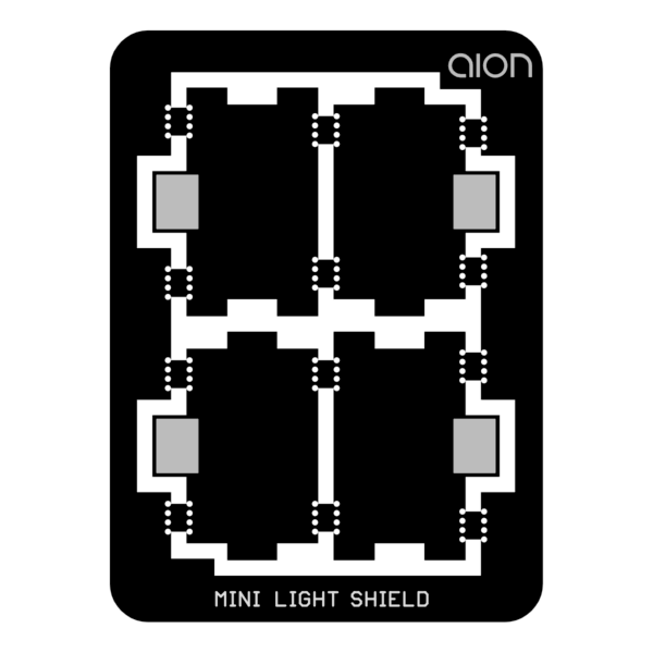
There is also an optional light shield that fits between the stacked PCBs. It seals the LDRs from outside light and also provides a reflective surface on the inside to better disperse the light from the LED.