Tracing Journal: Catalinbread® Supercharged Overdrive
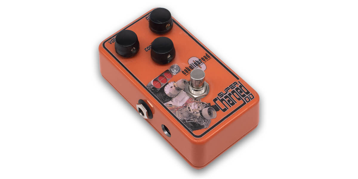
We’ve traced a whole bunch of Catalinbread pedals, and we’ve still got a few more on the way. The Supercharged Overdrive is an earlier design from their first few years as a company, predating their “Foundation” series of amp emulation circuits—but had it come a little later, it might have been included in the series as an Orange-flavored product.
Here’s a demo from Brett Kingman:
In 2007, Catalinbread said that one of their goals in designing the SCOD was to use “a particular semiconductor device that we hadn’t seen used for this type of application” (product copy from Effects Database). The SCOD was traced several years ago on Freestompboxes.org, so we knew that the “particular semiconductor” was a CD4007. But it was an early horizontal unit, and since Catalinbread has a history of tweaking products after launch, we thought it’d be good to get a later vertical unit (>2009) to see if they’d made any improvements.
Tracing photos


")

We’ve traced several Catalinbread pedals before, so no surprises on the inside. This was their typical construction method from around 2008 to 2014.
Schematic

As mentioned previously, the heart of the circuit is a CD4007 chip. The 4007 is similar in concept to the CD4049/4069, but with one major difference. Inverters are “complementary MOSFET” (CMOS), with each inverter being comprised of an N-channel and P-channel MOSFET. The CD4049 and CD4069 each have six inverters, with each inverter having two pins (an input and an output).
The CD4007 differs in that it provides separate access to the source and drain pins of both MOSFETs for two of the three inverters, allowing for more granular usage of the matched MOSFETs. The tradeoff is that it only has three CMOS pairs instead of six.
However… in the SCOD, the pins are tied together such that they are used as normal inverters—so the pedal doesn’t actually utilize the CD4007’s potential for different configurations. So while it does use a particular semiconductor that hasn’t been used in other CMOS drives, it’s used in a way that has definitely been seen before, so any possible advantage compared to a CD4049/4069 could only be attributed to differences in the chip specs.
Fortunately, that’s not the only thing differentiating the SCOD from other CMOS drives like the Red Llama or EHX Hot Tubes. The Contour control is an interesting method of controlling the tone, somewhat resembling the global feedback of a classic tube amplifier. In fact, it reminds me of the “resonance” or “regen” control on a phaser, feeding a variable amount of the filtered output back into an earlier stage, which sweetens the midrange and adds resonance. Whatever the case, it’s a very effective tone control that completely changes the character of the pedal across the sweep and really makes it a unique circuit.
Beyond that, the BS170 stages are basically just Jack Orman’s MOSFET Booster at the input and output with a few value tweaks. It was no secret that Nick was a fan of this circuit, since it’s the basis of their Super Chili Picoso and related booster pedals.
Compared to the original FSB trace, there are a few component differences, likely actual production changes as opposed to mistakes in the original trace. Referencing the above schematic, C1 was changed from 22n to 47n; C2 was changed from 1n to 2n2; and C13 was changed from 47n to 1uF.
It’s possible that C11 was 22n in early units, but this could also be a tracing error. If the capacitor was actually changed by a factor of 10, it would have significant tonal changes, but on the other hand it’s very easy to misread the code.
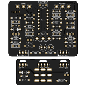 Calypso CMOS Drive
The Calypso CMOS Drive is releasing today, a straightforward implementation of the SCOD based on our trace.