Tracing Journal: Keeley Compressor Plus
The Keeley Compressor Plus was first released in 2017 as an update to their classic 4-knob compressor. Here’s a video demo from Andy Martin:
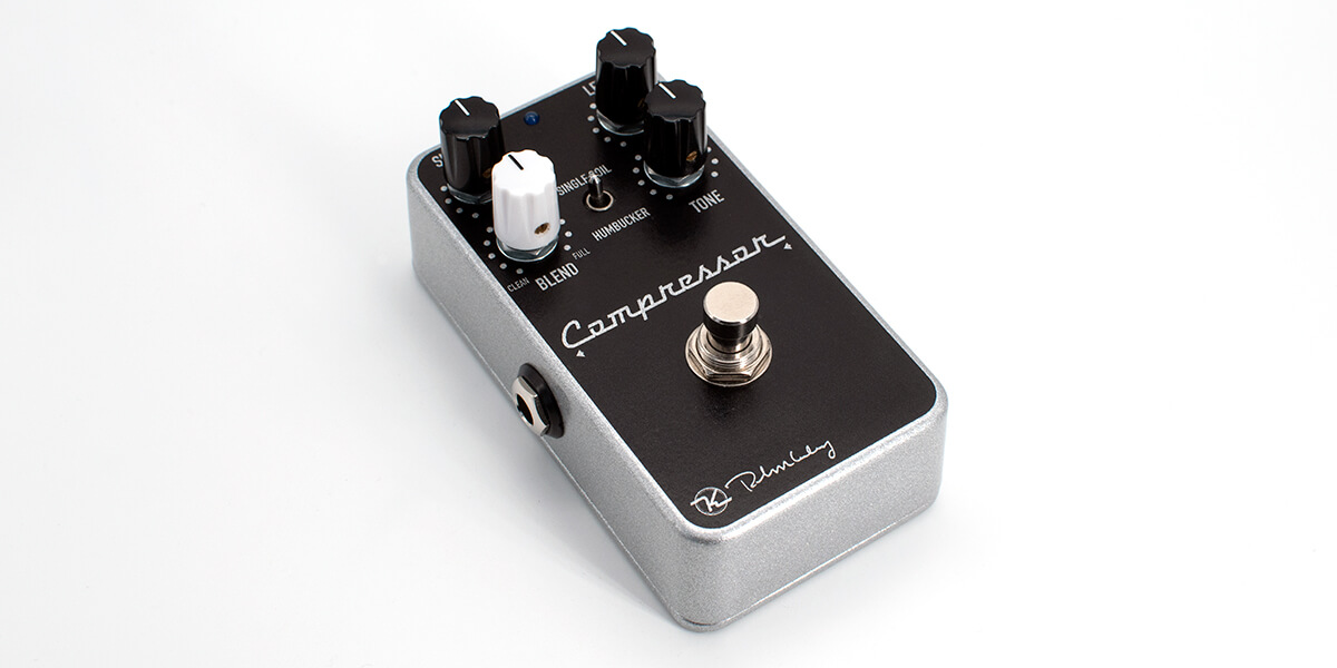
Compared to the earlier version, the input gain (anti-clipping) control has been removed and the Attack control has been converted to a switch, labeled as single coil / humbucker. From there, a clean blend and treble control were added.
This pedal fully replaced the existing Keeley Compressor in the product line, and in fact—aside from some limited-edition versions—they omitted the “Plus” from the enclosure artwork to further reinforce that it was the successor and not just an upgraded deluxe version.
Tracing photos

")
")
")
")
")
")


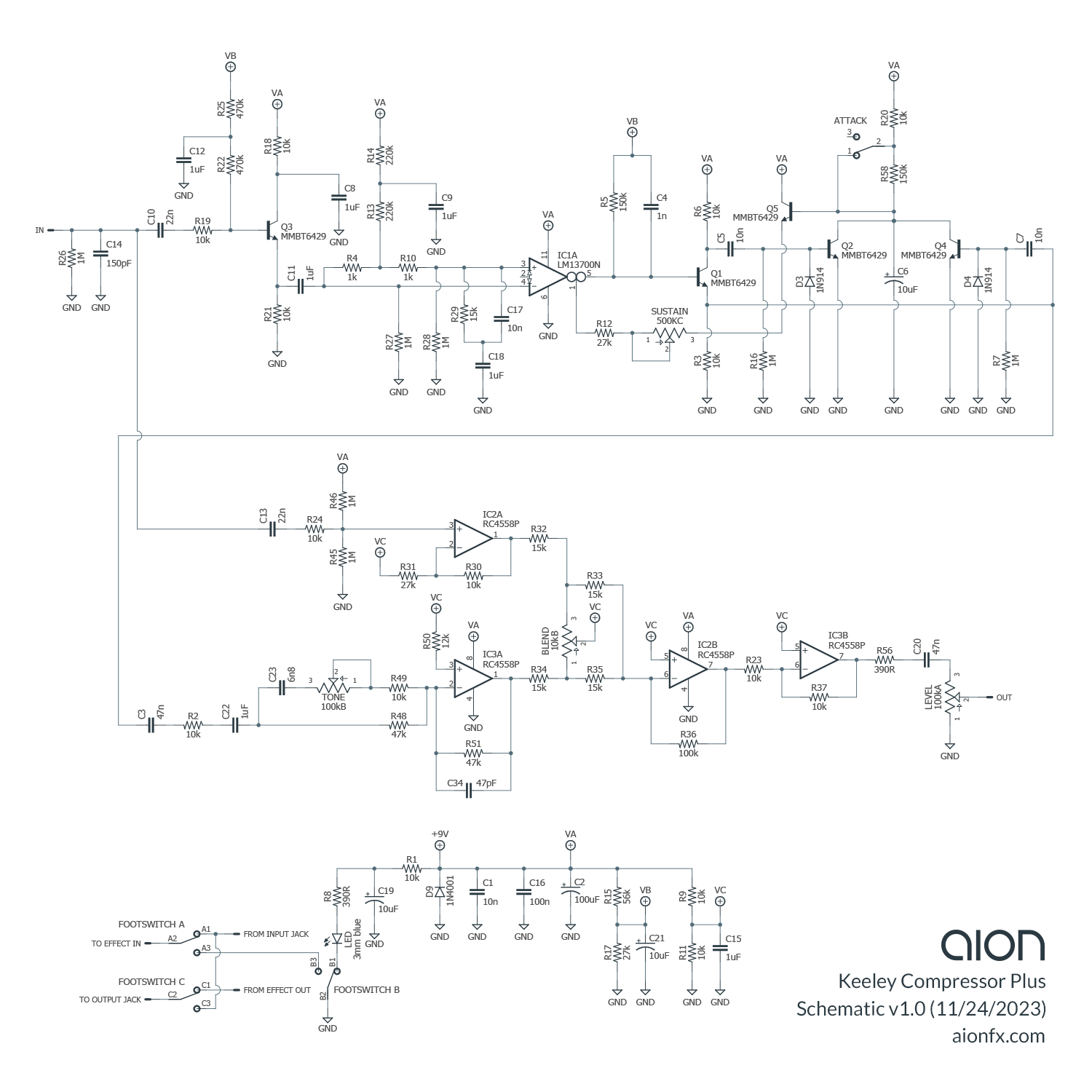
Schematic
Circuit variations
We referenced three different units for this trace:
- The first, with the black PCB, was an original 2017 unit and was the basis of the initial full trace as shown in the photos above.
- The second was from 2019 and had a green PCB.
- The third was from 2021 and also had a green PCB. This is the unit shown in the two photos above, partially disassembled. It was marked “Rev 2.3” on the reverse side. The two earlier ones had no version number on the PCB.
We used these to cross-reference several values for accuracy as well as to see if they had changed anything after 2017. All three had different layouts. But other than some significant layout changes—moving the 9V connector from one corner to the other and adding a ground spring—we only found one actual circuit difference, which is that the two dual op-amps had been changed from NE5532A to RC4558P in both of the green ones. It appears that the 5532 was only used in the original release and they’ve been using RC4558P since then. Therefore, in our schematic above, we specify the RC4558P. It’s a perfectly adequate op-amp used in many top-tier circuits and has a much lower current draw than the 5532.
Analysis
The majority of the circuit is exactly as expected, identical to the earlier 4-knob Keeley Compressor with the one major difference that the input clipping control, which attenuates high signal levels to prevent OTA clipping, has been removed, hard-wiring it to the full-up position (no attenuation). Other minor differences are a slightly larger input cap (22n instead of 10n), and a change from the CA3080 OTA to half of a LM13700.
The transistors are MMBT6429 (SMD code M1L), which is a high-gain low-noise surface-mount transistor, the SMD version of the long-obsolete 2N6429. They have very slightly lower noise spec than even the 2N5088 and BC549C, so they were most likely chosen for this characteristic in attempt to improve on the performance of the original compressor, which used 2N3904 transistors.
So, no big surprises in the compressor portion. Here’s a breakdown of the new additions.
Tone control
The tone control is interesting. Robert Keeley describes it (accurately) as follows:
The Tone Control is our own design taken from analog delays and other vintage effects. Those effects used an emphasis circuit to recover treble and highs after they went through the BBD or other analog delay lines. We took that circuit and made it into a full fledged tone control! We have found that it is the perfect way to gently add back in those highs lost in the compression process.
The type of circuit he’s referring to can be seen in the Boss CE-2 input stage, described in detail in this great article by ElectroSmash. By making the 10k resistor variable, the high-emphasis can be dampened as the resistance increases. The Compressor Plus even uses the same 6n8 tone capacitor as the CE-2.
Keeley’s description does get the technical specifics wrong, though: these analog BBD effects boosted the treble at the input, not the output, and it’s not to recover treble that is lost. Rather, these filters are designed to boost treble going into a noisy stage (the BBD chip itself, in the case of the CE-2) and then cut it afterward by the same amount, restoring the signal back to the original EQ but killing much of the hiss that was added along the way.
Regardless, it’s a creative way to get a treble boost and we have never seen this topology used as an actual tone control before.
Attack switch
The Attack knob from the earlier compressor has been converted to a switch, as on our Aurora and many other DIY implementations of the Ross/Dyna circuit. There is a noticeable change in the feel of the compression when comparing the minimum and maximum positions on the knob, but there’s almost no perceptible difference when going between 1 and 2 o’clock, for example—so a toggle switch that selects between zero and ten is definitely adequate.
The two switch positions are labeled with icons for “Single Coil” and “Humbucker”, but of course it’s purely a question of preference. The ideal setting typically has more to do with the playing style than the guitar’s configuration.
Blend circuit
Broadly speaking, it’s a pretty straightforward blend circuit. The blend is active, fading either the clean signal or effect signal to the bias voltage (which acts as ground to the audio signal) with a 50/50 ratio in the middle. The level control then sets the volume of the blended output. The tone control only applies to the effect side, so the clean signal is a straight buffered copy of the input. The mixing op-amp stage is inverting, and then it uses the second half of the op-amp to invert again, preserving the phase relationship between input and output.
There is a small design issue in the circuit—not so much a mistake, but an editorial oversight. At the end of the compressor section, there’s the typical 47n output capacitor and 10k series resistor, which would then go to the volume control in the original circuit. From there, the signal path instead goes into the blend circuit, which has its own 1uF input cap. This means that there’s a 47n capacitor, a 10k resistor, and a 1uF capacitor all in series.
Basic electronic theory tells us that when passive components are in series, the order does not matter—so all the 1uF capacitor does is drop the 47n capacitor to around 45n total capacitance. If the two circuits are hardwired together in the same enclosure, it’s a redundant component, and a single 47n capacitor would serve the same purpose.
This indicates that the blend/treble circuit was probably designed on a separate PCB or breadboard, likely taking the output from a standard-production Compressor with the volume knob removed, and they were then combined into one circuit in the layout phase. This is a sensible way of prototyping, but it does look sloppy to leave in the extra cap once the circuits are hard-wired together.[1]
Phase inversion
The classic MXR/Ross circuit inverts the signal, meaning you can’t use it in parallel paths or with an external blender like the Boss LS-2 unless there’s some method of phase correction in one of the paths. In the Compressor Plus, the compressor output goes into the tone control, which is an inverting stage, while the clean path buffer is non-inverting.
The blend stage once again inverts the signal, but the second half of the op-amp is used for phase correction which restores it back to +1. This means that, unlike the earlier Keeley Compressor and almost all other Ross/Dyna-derived circuits, the output of the Compressor Plus is in-phase with the input.
 Aurora Deluxe Compressor
Releasing today is our version of the Compressor Plus, called the Aurora Deluxe. It’s a direct adaptation of the Compressor Plus, but with one added feature: a third Attack setting, as on our original Aurora project, which simulates the 12:00 position of the original Attack knob. With settings for minimum, 12:00, and maximum, you won’t miss the knob. We also eliminated the redundant 1uF capacitor at the start of the blend circuit.
Notes & references
- Xotic did the same exact thing with the BB Preamp, which we discussed in our tracing journal for that circuit. As with this one it was almost certainly a relic of their prototyping process. ↩