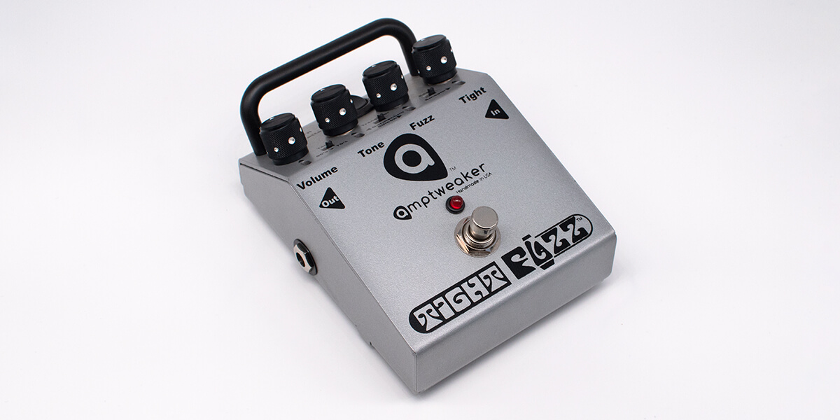
Tracing Journal: Amptweaker Tight Fuzz
The Amptweaker Tight Fuzz was first released in 2012, a year after the Tight Metal and two years after the Tight Drive. It was James Brown’s take on a classic transistor fuzz, but incorporating his characteristic design style and patterns.
Here’s a demo from Mike Hermans:
Fuzz, Tone and Volume are standard settings, while the namesake Tight control is a pre-gain bass cut. There is also a switch to select between silicon and germanium, as well as ’60s/’70s tone voicing and “Edge/Smooth” settings. Let’s have a look!
Tracing photos

")
")


")
")
")
")
")
")
")
")
")
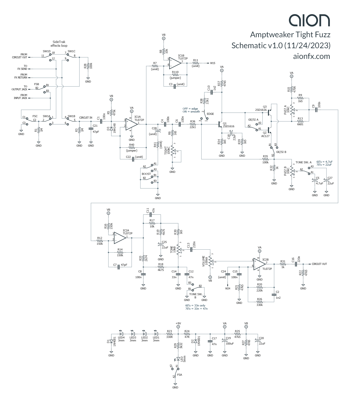
Schematic
Analysis
A lot that’s familiar compared to his other pedals, but it’s certainly the most unique of all the “Tight” series in the lineup. Here’s walkthrough of how it works.
- The input is a unity-gain buffer for consistent operation regardless of what comes before in the signal chain.
- The Tight control is a passive low-cut that immediately precedes the fuzz stage, similar to all the other pedals in the Tight series.
- The fuzz section is a two-transistor Fuzz Face-style sub-circuit using NPN transistors. The first transistor is silicon (2SD1616, equivalent to 2N5088 or BC549C) while the second one can be switched between silicon (another 2SD1616) or germanium (AC127). As the DIY community has shown (ref. Joe Gagan’s Easy Face), almost all of the germanium tone of the Fuzz Face comes from the second transistor, so there is very little difference whether Q1 is silicon or germanium.
- The Edge switch engages is a feedback R-C network between the base and collector of the first transistor. When this is active (called “smooth” mode), it cuts the highs and softens the edges somewhat.
- The Fuzz pot is a dual-ganged control that both increases the gain of the transistor and changes the bias across the rotation. The first half is similar to the gain control of a Fuzz Face, while the second half is the same as the Q2 bias trimmer in many DIY implementations (including our Solaris, Proteus and Epsilon). Two parallel resistors alter the taper and value of the bias-half of the potentiometer so that a standard type of potentiometer can be used as opposed to a custom-ordered type with two different values in each half, e.g. 10kC/1kB. Notably, it goes all the way down to a very-nearly-clean sound at zero, so you can get a great vintage-flavored boost without a lot of clipping. The traditional heavier fuzz tone doesn’t start until 2-3:00 on the rotation.
- The Tone switch selects between a 4.7uF and 22uF capacitor coming off the emitter gain control of the second transistor, which affects the low-end response of the fuzz section. 4.7uF is ’60s mode, while 22uF is ’70s and will have more bass. This switch is a double-pole switch that also has a second function in the tone stack, discussed below.
- For the Germanium/Silicon switch, the two collectors are tied together while a DPDT switch is used to switch the base and emitter. For some reason the base of the silicon transistor is always connected even in germanium mode, but really the emitters are all that matter.
- After the fuzz section, there’s a unity-gain inverting op-amp stage.
- Following this, there’s a Big Muff-style tone stack. On the low-cut side, there’s a 10k resistor in parallel with the capacitor, and a 22uF capacitor in series with the resistor to ground. On the hi-cut side, it’s a more complex two-pole filter that cuts at 581 Hz and either of two frequencies depending on the position of the Tone switch: 1k (’60s mode) or 419 Hz (’70s mode).
- Next is the Volume control followed by a final op-amp output stage. The op-amp stage recovers some volume lost by the passive tone stack, as well as cutting some of the highs in an almost identical manner to the Tight Fuzz and Tight Drive.
- There is also an effects loop called SideTrak. As with the other pedals in the Tight series, it’s engaged when the pedal is on. Internally, a slide switch controls whether the effects loop comes before the Tight Fuzz or afterward.
All in all, a pretty unique fuzz circuit that doesn’t really resemble anything else out there.
Transistors
The two silicon transistors (Q1 and Q3) are NEC 2SD1616, apparently old-stock. There is nothing unique about these transistors, so any medium-gain NPN such as 2N5088 or BC549C should perform the same.
The germanium transistor (Q2) is an AC127. As with the silicons, this is an NPN transistor, which is much less common than PNP, but avoids the need for a positive-ground circuit.
Unused parts
For curiosity’s sake, we drew out the full schematic of the PCB itself, not just a representation of the circuit circuit. You’ll notice it includes several jumpers and omitted components, particularly around the first op-amp stage.
There is an unpopulated slide switch labeled “Boost” whose surrounding components are omitted. It’s hard to tell what might be going on here, since all it does is ground an R-C combo right after the op-amp. However, if the second half of this slide switch had not been grounded, then it could handle some sort of switching with the IC1B op-amp stage. The grounding may have just been a quick fix before production to avoid a full redesign.
It’s also possible that W15 (a wire pad) was intended to connect to W24 in some way, which would mix the signal into the final op-amp stage by way of C24. This is further supported by the fact that the IC1B stage is inverting, so by putting the signal on the inverting pin of IC2B, it would flip the signal back to +1 and prevent phase issues.
So why was all of this left on the PCB? There is a video from the 2012 NAMM show where James Brown himself gives an overview of the pedal. It’s still in the prototype phase at this point, and he even brought a capacitor substitution box so NAMM attendees could help him decide on a few critical components for the overall voicing.
Since the pedal was released only a few months later, it seems likely that he kept the same PCB design and the layout included a few leftover ideas from the development process.
Whatever the case, the Tight Fuzz Pro from 2015 does have a boost feature by way of a footswitch, so it seems that whatever ideas he abandoned for the Tight Fuzz were eventually recycled.
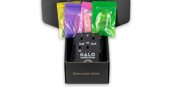
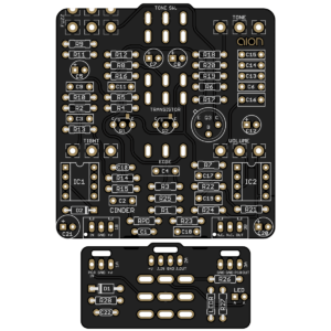 Cinder Hybrid Fuzz
Releasing today is our version of the Tight Fuzz, called the Cinder. We managed to fit the whole circuit (including all three toggle switches) into a 125B enclosure, excluding the SideTrak effects loop.