Tracing Journal: Amptweaker Tight Drive
Next up we have the Amptweaker Tight Drive. This is the very first pedal from Amptweaker, the pedal company founded by amp guru James Brown, designer of the legendary Peavey 5150 amplifier among many others. Released in 2010, it predated the Tight Metal and Tight Rock by a year. Here’s a demo video from Mike Hermans:
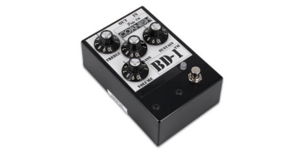
The chassis is familiar, but unlike all of his later designs, there are no toggle switches on the front. It has the same “Tight” control, which is likely a variable low-cut that comes before the distortion, one of James’s trademarks found in all the other drive pedals and many of his amps. But other than that, how similar is it to the Tight Metal?
Tracing photos


")


")
")
")
")

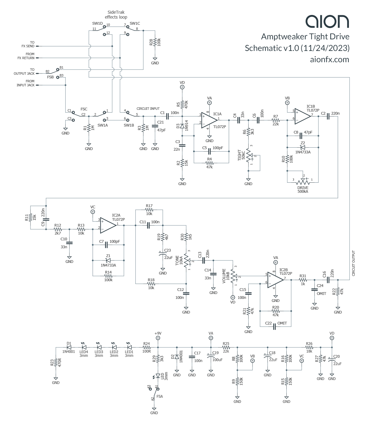
Schematic
Analysis
As it turns out, pretty similar. Compared to the Tight Metal and Tight Drive (which are 95% the same as each other, just voiced differently), it has the following differences:
- The Tight Drive omits the initial clipping stage that comes before the Tight control
- No noise gate
- No midrange shaping after the tone stack
- No hi-cut in the op-amp output stage
Apart from those, the topology is about the same: input boost, variable low cut, clipping stage, clipping stage, Big Muff-style tone control, volume control, gain recovery. It’s not hard to see the progression from the earlier circuits to the later circuits. While they don’t resemble anything else, there is continuity of design throughout each of them.
As with his other pedals, it has an effects loop called “SideTrak”, which engages the send/return jacks when the pedal is in effect mode. This loop can be set to come either before or after the Tight Drive, circumventing the need for complicated loop switching to turn on a series of pedals for a certain sound.
Unused components
Two capacitors near the end of the circuit are unpopulated on the PCB. C22 is an op-amp feedback capacitor to prevent oscillation, while C24 forms a low-pass filter to cut highs in conjunction with R31.
As configured, the final op-amp stage gives a gain of 2.[1] The presence of C22 indicates that the output op-amp stage was likely originally designed to have higher gain, since the feedback capacitor is not needed if the op-amp amplifies the signal only a small amount.
C24 indicates that there was originally some added tone shaping at the end, possibly to correct for an otherwise overly bright circuit. It’s possible the tone stack was tweaked in order to remove this brightness so that the hi-cut was no longer needed.
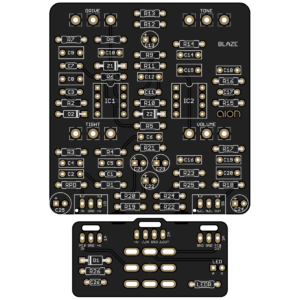
Blaze Dynamic Overdrive
Releasing today is the Blaze, our take on the Tight Drive. It’s a straight adaptation based on our trace, but without the SideTrak effects loop. We added a bit of extra filtering on the power supply and reference voltages, but otherwise it’s the same as the original. We left space for the extra capacitors in case you want to experiment with increasing the gain, but these should normally be omitted.
Notes & references
- A non-inverting configuration has a base gain of 1, while the 47k+47k resistor ratio adds a gain of 1, with a low-cut below 34 Hz due to the 100n capacitor. ↩