Tracing Journal: Seymour Duncan Pickup Booster
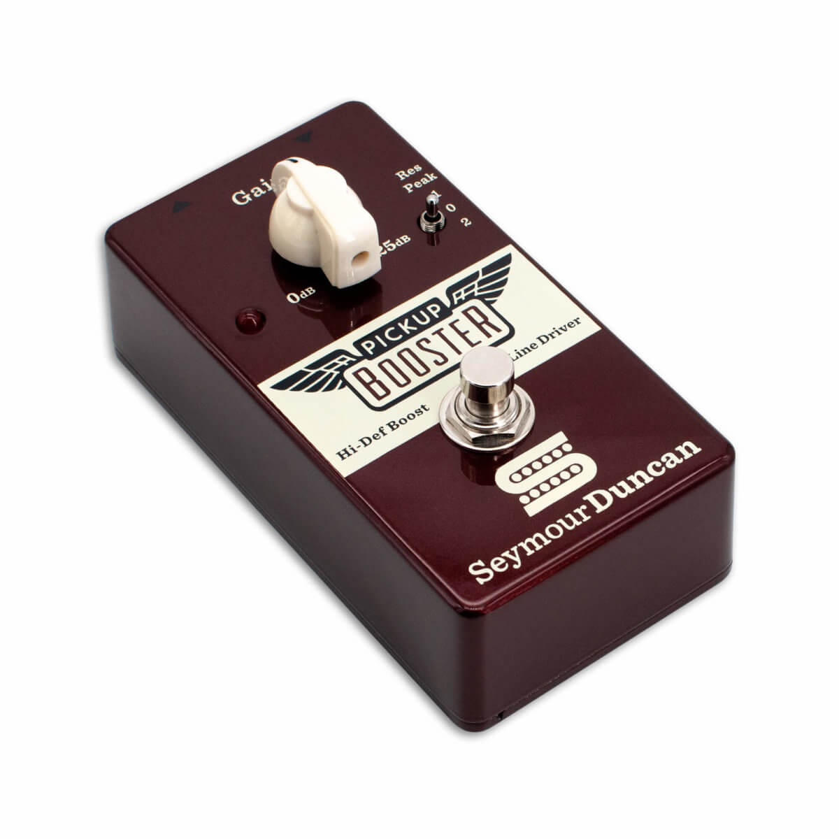
The Seymour Duncan Pickup Booster is a clean boost pedal with the added feature of being able to simulate the resonant peak of different pickups, letting a single-coil assume the character of either vintage or modern humbucker. It was first released in 2004, discontinued for awhile, and then resurrected in 2015 with an improved Class A design.
Here’s the intro video from Seymour Duncan themselves:
Now, here’s the deal. Seymour Duncan is a great company. The build quality and aesthetics of the Pickup Booster are good, and they’re very reasonably priced, even new. So if you build one yourself, the overall cost savings ratio isn’t killer.
But, I used to own the first version when it originally came out, and it always struck me as an interesting circuit. The 2015 update hadn’t been traced yet so I wanted to see what had changed.
Schematic
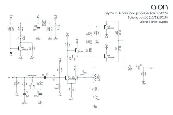
I didn’t get any good photos of the inside of this one, and we had to destroy the SMD board to trace it. But here’s the schematic:
Here’s the PDF version.
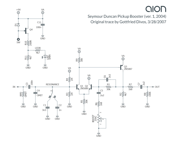
Compare it to the schematic from version 1 (redrawn from Analogguru’s trace in 2007):
Analysis
As you can see from comparing the schematics, the major difference in version 2 is the addition of a Class A push-pull output stage instead of the single PNP transistor. The Boost control has also been rearranged so that the pedal can go all the way down to unity gain. (One of the quirks of the original is that there was always some amount of signal boost even at the lowest setting.)
The new version uses uncommon and specific resistor values such as 30.1k and 4.77k. You tend to see more of this type of thing in SMD work. There isn’t any engineering reason for this amount of precision, so the nearest common value would work just as well, such as 30k or 4.7k.
One other thing to note is the lack of power filtering. There’s a single 220nF capacitor on the +V supply, and then Vref has a 4.7uF filter capacitor. Interestingly, though, there was a mistake in the PCB layout and the 4.7uF capacitor isn’t actually connected to the ground plane like it should be. It’s just a dead-end. The unit we traced was manufactured in 2018, so it’s likely an issue with all versions going back to 2015. It was easy to tell what they meant to do, so for the schematic I went ahead and corrected this mistake.
Photon Booster / Line Driver
The Photon Booster / Line Driver is a new Aion FX project based on the Pickup Booster. It’s a direct clone with no added features other than standardized (and improved) power filtering.
The high-precision resistor values used in the original have been carried over to the DIY version since they were all available in through-hole format at Mouser. However, the circuit should perform identically using more common values, so if you aren’t ordering from Mouser, we’ve provided a list of more common substitutes in the documentation.
Disclaimer: Aion FX is not affiliated with Seymour Duncan. All trademarks are property of their respective owners and used for comparative purposes only.
