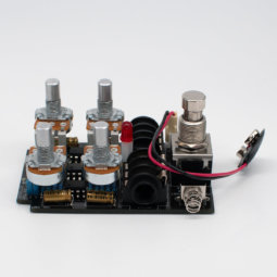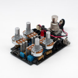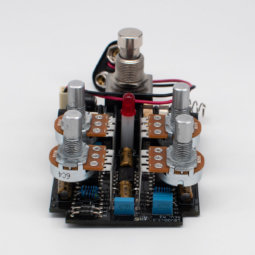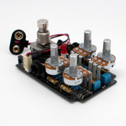
Tracing Journal: Mr. Black Thunderclaw
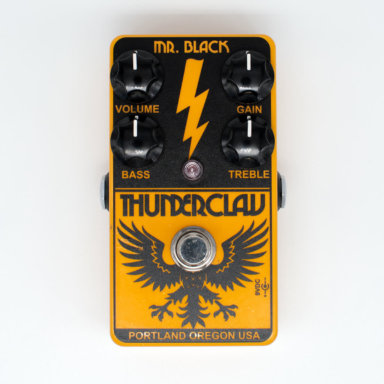
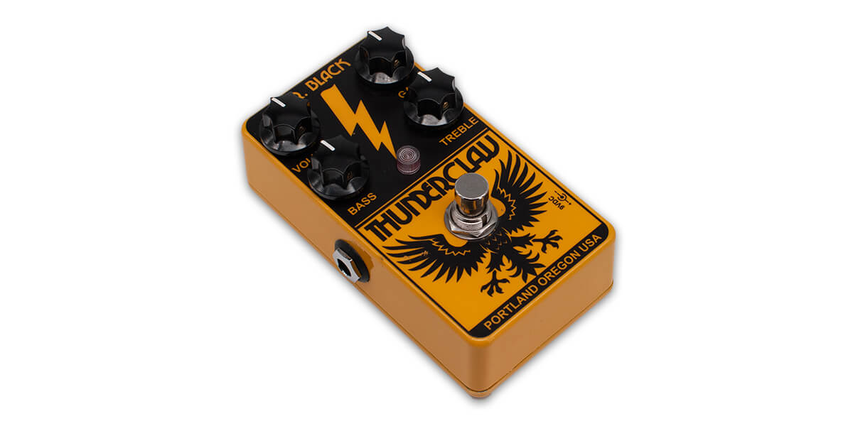
The Mr. Black Thunderclaw is a high-gain distortion with a two-band EQ originally released in 2014.
Here’s a straightforward demo of the Thunderclaw by The GAS Station:
It was traced by PedalPCB and released as the Kittywampus Distortion earlier this year, but as of this writing the documentation has not been added and no schematic has been shared. We’ve had one of own in the tracing queue for awhile now, so we decided it was a good time to take it apart and see what was inside.
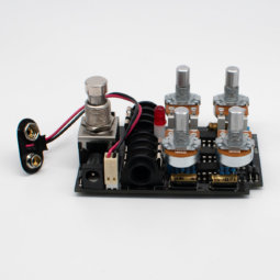
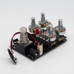
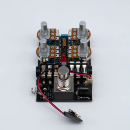
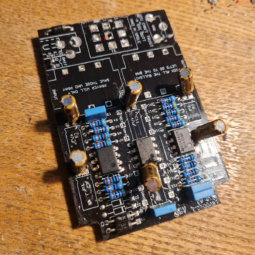
Tracing photos
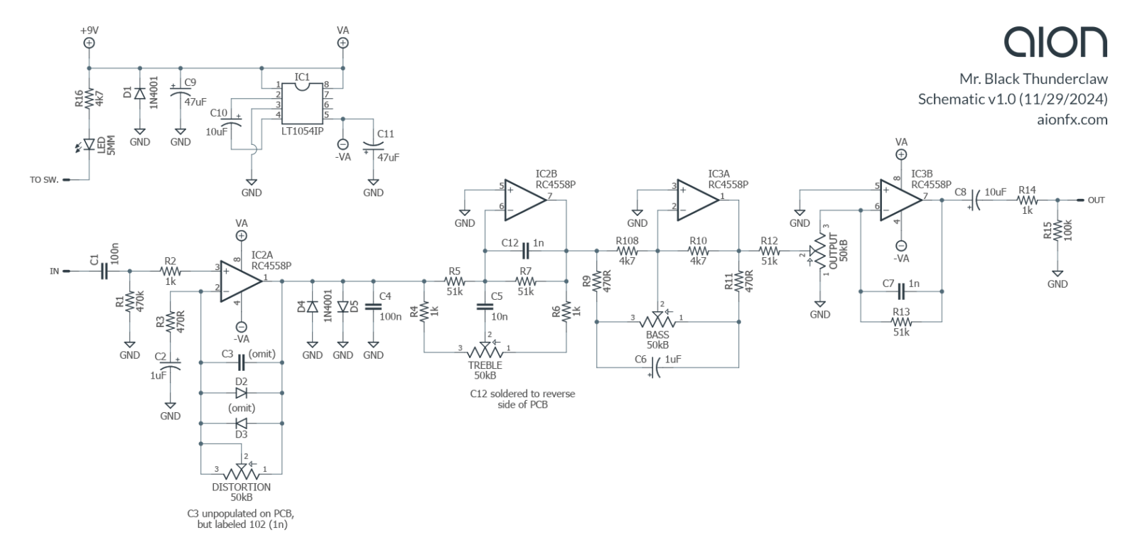
Schematic
Analysis
The Thunderclaw is not strictly based on any existing pedal, though it does use several building blocks from other distortion designs:
- The input & clipping sections resemble a RAT with a clean op-amp boost into back-to-back diodes to ground.
- The two cascaded tone controls are similar to single-band Baxandalls and have some resemblance to the Tube Screamer tone control, both of which have boost and cut capabilities like these controls, though we haven’t seen this exact topology in other circuits.
- Charge pumps are common in drive pedals, but it’s more often a voltage doubler (+9V to +18V), whereas bipolar supplies (+/-9V) are more closely associated with preamps and other professional audio gear.
- The active volume control is a great solution for a constant output impedance—a fairly straightforward op-amp application, but we haven’t seen it done exactly like this.
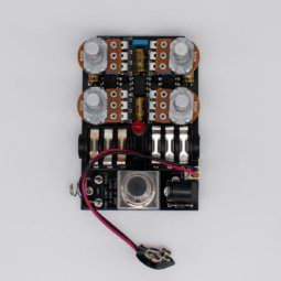
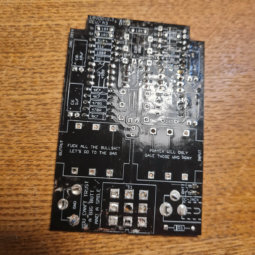
This is an interesting case where the PCB itself gives some clues to the design process, similar to the King Tone Octaland. There are a few parts that are unpopulated on the board, most notably diodes in the feedback loop of the first op-amp that indicate that at some point Jack may have originally experimented with dual-stage clipping (as in the Nobels ODR-1) or that he was trying to decide between the two configurations. Our schematic matches the PedalPCB project which also shows only two clipping diodes to ground, so the two traced units are identical. It was most likely left over from the development process before release as opposed to a revision after production began.
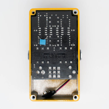
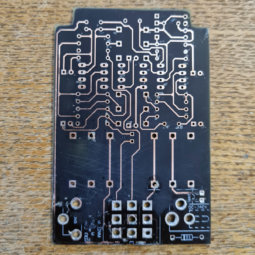
The D4 diode also has pads for a capacitor stacked in the same position, which you can see in the photos of the PCB with components removed. This capacitor is in the op-amp feedback loop, in parallel with the unused set of diodes. It’s labeled 1n, which means it would cut treble at ~3.2k with the distortion control at max, and would soften the diode clipping somewhat if those diodes were included.
There is also a 1n capacitor that has been added to the reverse of the PCB in parallel with R7. This indicates a late addition once the rest of the circuit was finalized. As with the capacitor in the first stage, it cuts treble above approximately 3.2k, essentially limiting the high end of the treble control. It’s also present in the PedalPCB project, so it’s likely that all production units have this capacitor.
Update, 4/5/2025: We mistakenly listed R4 and R6 as 1k in the original schematic. These resistors limit the maximum and minimum rotation of the Treble control. They are marked 1k on the PCB silkscreen, but populated with 4.7k resistors, as can be see in the photo with the components partially unpopulated. This is another indication of a late change, after the PCB was finalized but before full production. 4.7k resistors will restrict the treble boost/cut range very slightly compared to 1k, reducing both extremes by around 5%, but the 12:00 position will still be the same.
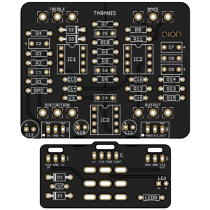 Taranis Dynamic Distortion
Releasing today is our version of the Thunderclaw circuit, called the Taranis Dynamic Distortion. It’s a direct adaptation, with a small amount of added power filtering as well as a zener overvoltage protection diode but no modifications or added features.
