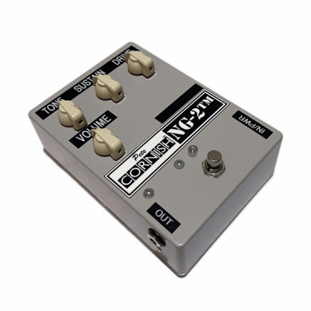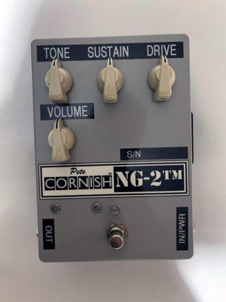
Tracing Journal: Cornish NG-2
Today we unravel a mystery! For context, last year we traced the Cornish NG-3. That tracing journal has a full history of all of the “NG” circuits (the N.G. Fuzz, NG-2 and NG-3) and we will only be repeating part of it here, so if you want the full context for this trace, we recommend reading that post first.
Now we’ve done the NG-2 as well and are finally able to answer the open questions from the NG-3 trace.
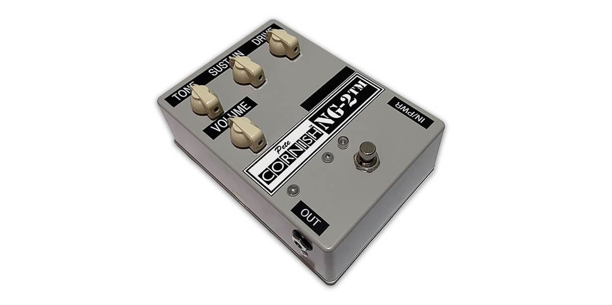
Other than Lou Reed, for whom it was originally designed, the NG-2 was most famously used by John Mayer for his version of Crossroads in 2009. Here’s a demo from John Nathan Cordry:
According to Pete, the only difference between the NG-2 and the NG-3 is that the internal bias control was moved to the front panel in the NG-3 for access to a wider array of sounds:
When I supplied the first NG-2 to Lou Reed I mentioned that there was an internal bias control that I set during testing. Lou asked if this could be made external so that he could adjust it to find other possibilities. As this was very successful I decided to add the Bias control as a user adjustable control and hence called the pedal the NG-3 to differentiate it from earlier versions. There is no audio difference between the NG-2 and NG-3 just the possibility of user adjustable Bias control.[1]
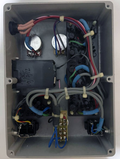
Having traced both pedals now, we can say definitively that this is not true. But first let’s have a look inside this unit from 2012.
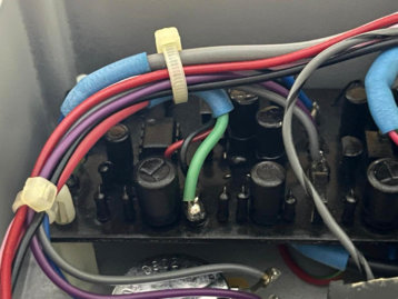
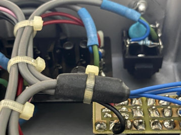
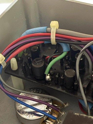
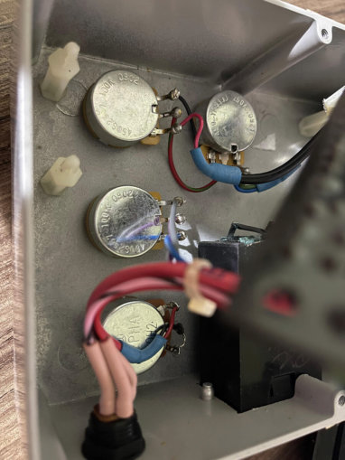
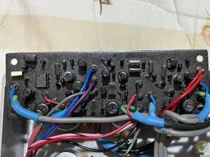
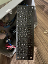
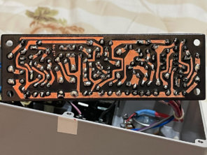
Tracing photos
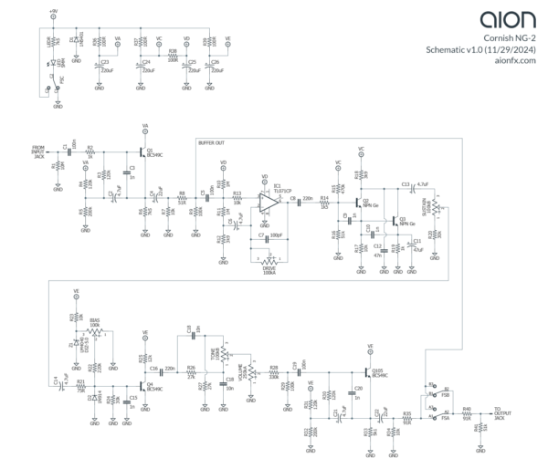
Schematic
Some technical data about the transistors and bias trimmer:
- Q2 tested at 376 hFE, 1429µA leakage (5mA test current)
- Q3 tested at 359 hFE, 1376µA leakage (5mA test current)
- Bias trimmer was set to 90.7% rotation (trimmer measured 97.75k from pins 1-3 and was set to 88.64k between pins 1 and 2)
- Bias voltage was 4.36V at pin 2 of bias trimmer
Analysis
Right away, you can see the major difference: the clipping stage, which comes right after the op-amp boost, is made of two NPN germanium transistors instead of the single silicon of the NG-3. This explains why the only difference in the text description for the NG-2 and NG-3 is the word “germanium” in describing the preamp, which has been replaced with the word “discrete” in the NG-3. But, it directly contradicts his statement above that the two models only differ in the bias control.
NG-2 vs. NG-3 differences
Other than the germanium stage, the rest of the changes are fairly inconsequential. Here are the specific differences between the NG-2 and NG-3.
- Drive control: The resistor that sets the gain ratio of the op-amp stage (R12) is 3k9 in the NG-2 and 3k3 in the NG-3, meaning the NG-3 will be capable of slightly more maximum gain going into the germanium stage.
- Germanium preamp: The NG-2 has two germanium transistors instead of one silicon. Accordingly, the bias resistors are different, including one additional resistor in the NG-2 to support the second transistor. There is also another 1n cap from base to emitter of the 2nd transistor, as well as a 47n capacitor to ground which cuts the treble coming out of the preamp stage. The 22µF emitter bypass capacitor has been increased to 47µF.
- Bias control: The bias control is a trimmer in the NG-2 and a potentiometer in the NG-3. The NG-3 has a 68k limiting resistor on the CCW side of the potentiometer while the NG-2’s bias trimmer just connects directly to ground on that side.
- Tone control resistors: The NG-2 uses 27k resistors for R26 and R27 while the NG-3 uses 28k. There would be almost no difference in tone between the two values and it’s probably just due to availability. It could also have been a revision made to both units at the same time since our two traced units were manufactured several years apart.
- Coupling resistor: The resistor going into the “amp death” bias stage is 75R in the NG-2 and 82R in the NG-3. Again, no difference and it may be due to availability or a revision to both units.
- Power filter resistors: R37-39 are 100R in the NG-2 and 150R in the NG-3.
Transistor selection
The transistors were unmarked, so we’re not sure of the type exactly. The specs would typically be considered unusable for fuzz circuits: very high gain and an extraordinary amount of leakage. But due to the way they are configured, the actual specs probably don’t matter very much and you can get away with just about anything. For our prototype, we used Soviet NPNs with hFE around 140 and leakage under 100µA and they worked great.
PedalPCB Nugget
We should also return to the question of the PedalPCB Nugget. This project was initially released in 2018 and said to be a trace of the Cornish NG-2. After tracing the NG-3, we shared our doubts that the traced unit was a stock NG-2 since it had nothing in common with the NG-3 from our trace. And now that we’ve traced an NG-2, we can confirm that the Nugget is not a NG-2.
We’ve seen a few one-off Cornish circuits and parts of integrated rigs that had been disassembled and sold off separately, so it’s possible the traced unit had been mislabeled as an NG-2. As we said in the NG-3 article, the schematic does look like an authentic Cornish design and each of the four stages has similarities to other Cornish circuits. But the fact that it’s missing his famous buffers means it could not have come from a standard-issue single pedal.
There are several DIY implementations that are sourced from the Nugget schematic. The Fuzzdog N-er-Getic Fuzz and PCB Guitar Mania Cornic Fuzz are two, and there are also vero/perf layouts like the one from Dirtbox Layouts.
So in the interest of accuracy, now that we are contributing a very different NG-2 schematic to the DIY community, we need to state clearly: all NG-2 schematics and layouts from before November 2024 are incorrect. This is the first time that a real NG-2 has been traced.
 Nysiad Germanium Fuzz
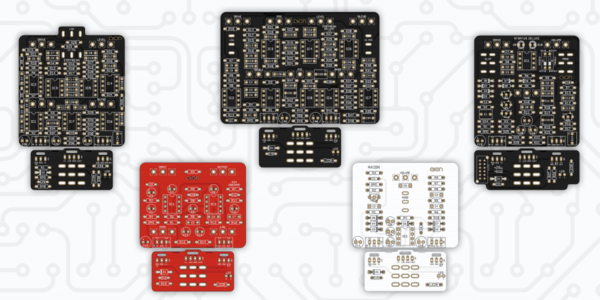
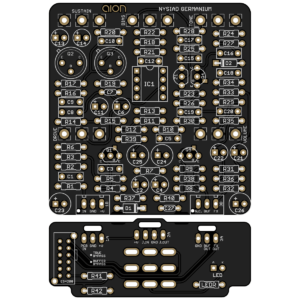
Along with the trace, we are releasing an alternate version of last year’s NG-3 PCB called the Nysiad Germanium Fuzz. While much of the circuit is common between the two, the germanium transistors prevent the NG-2 from being built on the NG-3 board as a variant. We kept the bias knob as an external control since it works just as well in this circuit.
Notes & references
- Quoted from an email exchange with Pete posted on thefretboard.co.uk in 2017. ↩
