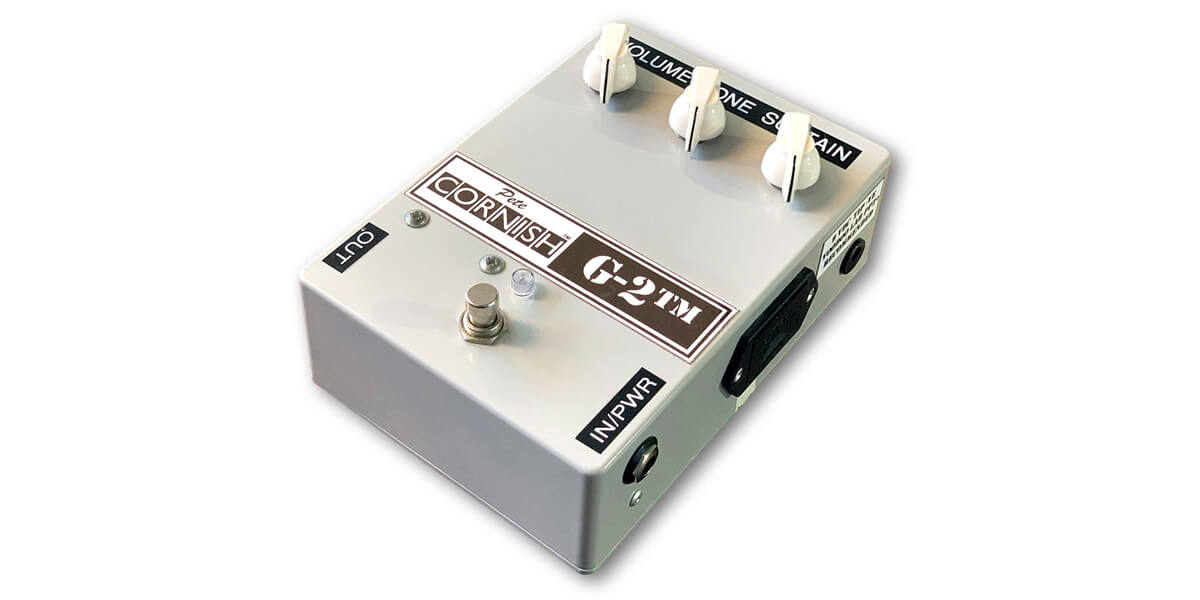
Tracing Journal: Cornish G-2 (two versions)
Today we’ve got a few new Cornish traces to share. Along with the P-1 detailed in another post, we have not one, but two versions of the Cornish G-2.
The G-2 was originally designed by Pete for Lou Reed in the 1990s. Here’s a demo by Simon Gotthelf:
The G-2 has a long history in the DIY community. In 2009, it became one of the first high-profile FSB traces, with dozens of forum members contributing to a fund to purchase one to take apart. Until then, it was not known to have been a Big Muff variant, but the familiar topology was quickly apparent once the goop was removed. It’s a Big Muff with Cornish buffers and a simplified tone control. The “G” designation is due to the germanium diodes. There are a number of other value tweaks throughout the circuit and the end result doesn’t sound much like a classic Big Muff.
Over the past fifteen years, it’s given a lot of trouble to those building it. The second clipping stage is very finicky and sometimes does not pass signal at all. It’s been speculated that there were mistakes in the original trace, but no one’s been able to confirm anything other than a couple of minor transcription errors. Rather, it seems that the circuit itself is at fault, and that the transistor biasing scheme is dependent on a very specific type of germanium diode. If the diodes’ forward voltage is too low or the leakage is too high, then it won’t bias right and won’t pass signal.
Several modifications have turned up to fix the issues, rebiasing the transistor to be more tolerant of different types of diodes. But since the original unit was from 2006, it’s always been an open question whether 1) the trace was wrong, 2) Pete has avoided these issues by some other means, or 3) the issues necessitated changing the circuit at some point along the way.
The two units traced in today’s journal were from 2008 (grey series) and 2012 (battery-free), so they should be able to provide us some answers. Here’s what was inside.
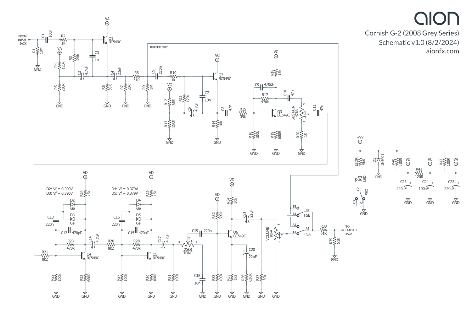
2008 Grey Series
Trace photos
 Inside Enclosure")
 Inside Enclosure 2")
 Inside Enclosure 3")
 Inside Enclosure 4")
 Buffer PCB")
 Main PCB, Reverse")
 Main PCB, Reverse 2")
Schematic
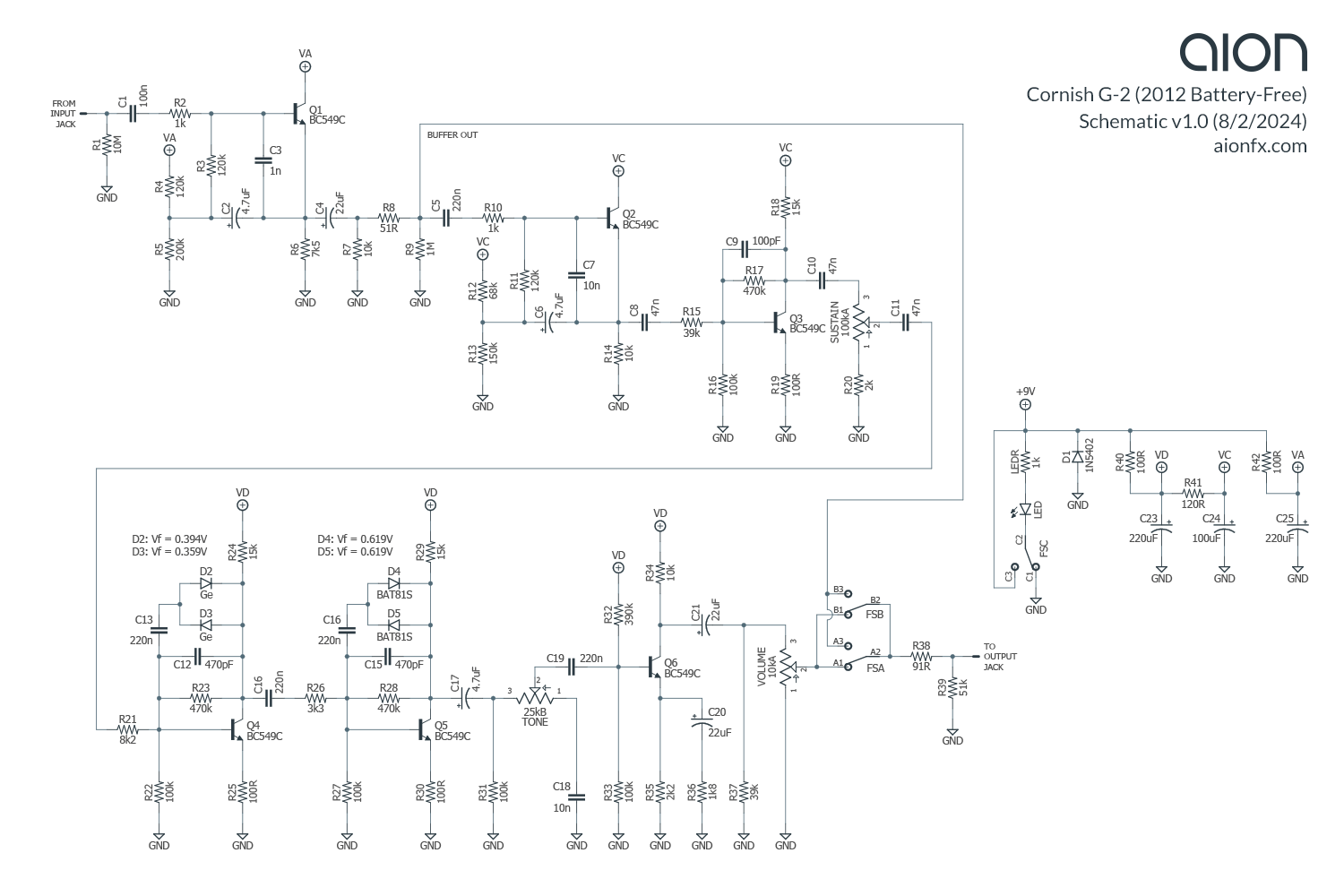
2012 Battery-Free Series
Trace photos
 - Inside")
 - Inside 2")
 - Inside 3")
 - PCB")
 - PCB - Components")
 - PCB - Diodes")
 - Potentiometers")
 - PCB Traces")
Schematic
Analysis
These two traces offer several new details for the G-2 circuit. In total, there are nine differences between the 2008 and 2012 units, and the 2008 unit has seven further differences from the original G-2 trace.
2008–2012 changes
Here are the differences between the 2008 and 2012 units traced here.[1]
- D4-D5 clipping diodes: The most notable change between 2008 and 2012 is that the second pair of clipping diodes (D4 and D5, the problematic pair) has been replaced entirely. Now only the first stage uses germanium while the second pair uses BAT81S Schottky. These diodes have a pretty high clipping threshold compared to other Schottkys and should be almost indistinguishable from the standard 1N914 silicon type.
- C9 feedback capacitor: The feedback capacitor in the first amplifier stage, C9, is 470pF in the 2008 unit. It has been reduced to 100pF in the 2012 unit. This restores a bit of the high end before the two clipping stages.
- C14 coupling capacitor: The 4.7uF electrolytic coupling capacitor between the first and second clipping stages, C14 has been reduced to 220n and changed to film. This seems like it would cut some bass, but due to the low output impedance of the transistor stage, any difference would likely be below the useful audio range.
- R26 resistor: The 8k2 resistor in series with C14 is changed to 3k3 in the 2012 version.
- R19 and R25 emitter resistors: In both the first amplifier stage and first clipping stage, the emitter resistors R19 and R25 have been reduced from 680R in 2008 to 100R in 2012, which increases the gain of both stages. These are the values used in the P-2 as well as most variants of the original Big Muff.
- Sustain pot and R20: The Sustain potentiometer and the corresponding minimum-gain resistor have both been doubled. In the 2008 version, Sustain is 47kA, and was increased to 100kA in the 2012 unit. The resistor that sets the minimum gain, R20, has been increased from 1k to 2k, which is a proportional increase. Neither of these should have much impact on the tone since it is a simple volume-control voltage divider. The maximum and minimum gain aren’t affected, only the impedance ratios between the stages. It was likely changed to correspond with the increased gain of the stages immediately before and after.
- R36 emitter bypass resistor: The last change is the resistor in series with the emitter bypass cap in the gain recovery stage, R36. In the 2008 version, it’s 620R, but it’s been tripled to 1k8 in the 2012 version. This essentially reduces the bass boost in this stage by a factor of 2/3, which should have a fairly significant impact on the overall bass content at the output. The G-2 is known for being bass-heavy, so this is undoubtedly an improvement.
2009 trace differences
The 2008 unit has the following differences from the original 2006 unit, traced at Freestompboxes.org in 2009:
- R7 buffer output resistor: When developing the original Cygnus project, we speculated that the 20k resistor at the output of the first buffer, R7, was an error in the trace, since this resistor was 10k in all seven of the Cornish pedals we traced ourselves. But as you can see in our 2008 trace, it was in fact 20k originally, and was changed to 10k at some point between 2008 and 2012. So the original G-2 trace was correct here.
- R14 buffer emitter resistor: The emitter resistor of the second buffer stage, R14, was 8k2 in the original trace. In the 2008 version, it has been increased to 10k, which is the same as the P-2. This has no impact on the gain or tone since it is just a buffer stage.
- C9, C12 and C15 feedback capacitors: In the first amplifier stage and the two clipping stages, the feedback capacitors C9, C12 and C15 were 1n in the original trace. In the 2008 version, all three were reduced to 470pF, the same as the P-2. This reduces the amount of hi-cut in these stages, and would probably have a fairly significant audible effect. The 2006 G-2 was very much lacking in treble, so this is a step in the right direction.
- R34 collector resistor: In the gain recovery stage after the tone control, the collector resistor R34 was 8k2 in the original trace. In the 2008 version, it has been increased to 10k, again the same as the P-2. This increases the gain of the last stage very slightly.
- R39 output pull-down resistor: The other possible error we had noted was the output pull-down resistor R39, which was listed as 50k in the original G-2 trace but was 51k in all of the units we’ve traced. Both the 2008 and 2012 units use 51k here, and given that 50k is a non-standard resistor value, we are confident in saying this was a transcription error in the original G-2 trace. It is entirely inconsequential, only affecting the output impedance by about 2%, but we try to be meticulous.
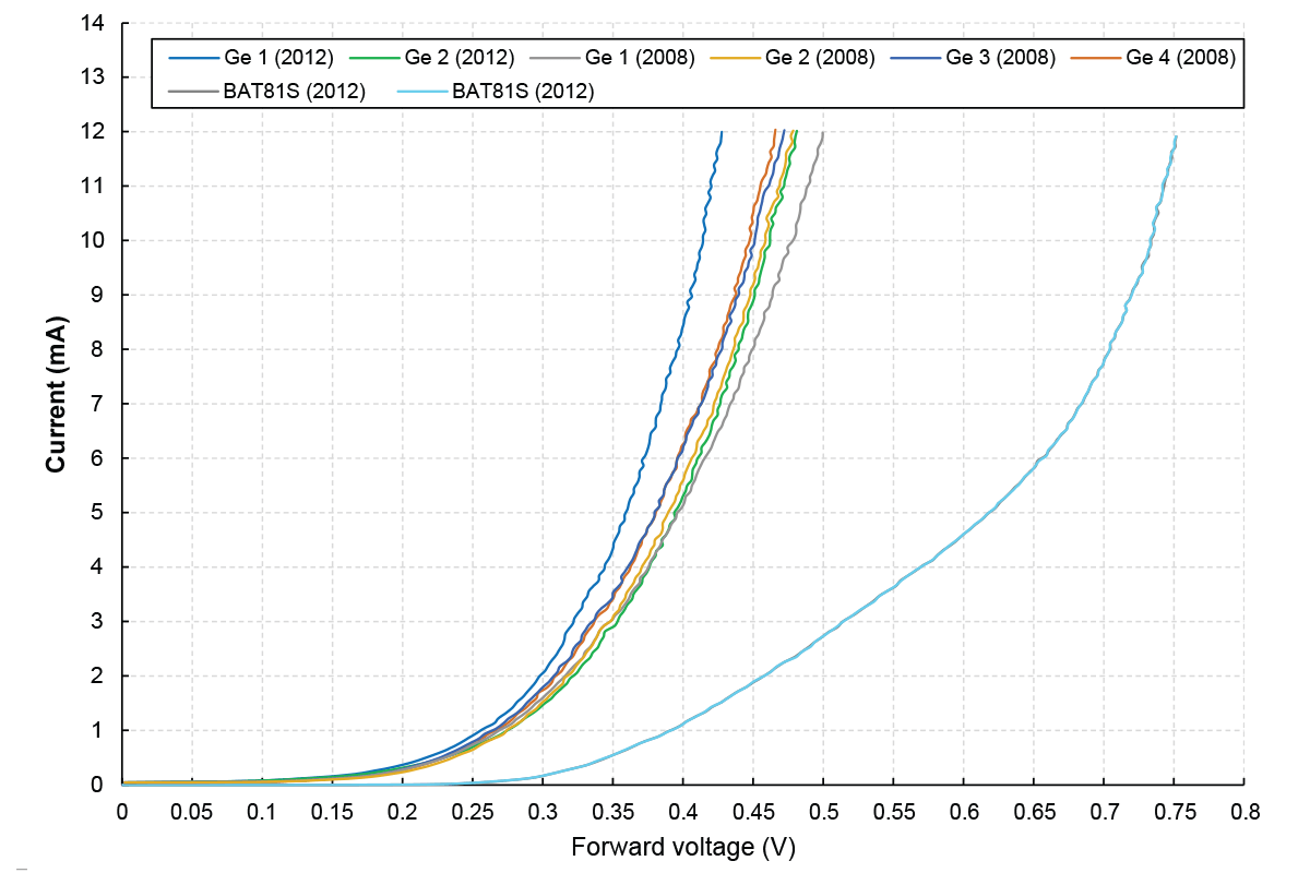
Diode measurements
We’ve also got some measurements on the diodes. Using a Peak Atlas DCA75, which has a 5mA test current, all six germanium diodes (four in the ’08 unit and two in the ’12 unit) measure between 0.36V and 0.4V forward voltage (exact values noted on the schematics). This is a fair amount higher than most germanium diodes, which more often fall in the 0.2V to 0.3V range, and it helps to explain why people have so much trouble getting the second stage to bias correctly. Anecdotally it had always seemed that people had better luck when using higher forward voltages, and this is supported by these diode measurements.
Here are the exact diode forward voltage curves if you’re curious:
Grey Series vs. Battery-Free
One last point of discussion. Both the 2008 unit and the 2006 unit from the original trace were Grey Series, while the newer 2012 unit was a black Battery-Free model. It’s reasonable to wonder if the difference in model is more significant than the difference in year. In other words: should we be calling them the 2008 vs. 2012 versions of the circuit, or are we actually looking at the differences between Grey and Black?
Pete insists that the Battery-Free series is nothing more than a compact version of the Grey Series, and none of these changes are related to the battery. The early G-2 circuit is known to be flawed and all of these changes seem to be improvements, including correcting some design issues that make it very picky about the parts used. So based on this, we’d hypothesize that a newer Grey Series would have more in common with the 2012 unit than with the 2008 unit. But until someone takes apart a Grey Series from 2012 or later, we can’t know for sure.
Cygnus Distortion/Sustainer
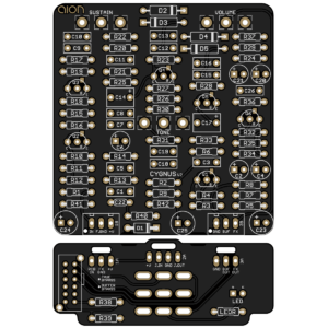 We’ve had a project based on the G-2 for a long time now, the Cygnus Distortion/Sustainer, which received a major update after we traced the P-2 last year. There are no PCB changes to go along with this updated G-2 trace, but we have updated the documentation to correspond to the latest version of the G-2 because it’s a big improvement over the original.
Disclaimer: Aion FX is in no way affiliated with Pete Cornish. Any trademarks are property of their owners and are used for comparative purposes only.
Notes & references
- There are two more inconsequential changes not listed: the LED resistor has been reduced from 5k6 to 1k, which compensates for the different LED used in the battery-free version. The D1 polarity protection diode has been changed from 1N5401 to 1N5402, which has a 200V max reverse voltage compared to the 5401’s 100V. Both diodes far exceed the voltage for this circuit so it was probably just substituted due to availability or price. ↩