Tracing Journal: Revisiting the Original Honey Bee FSB Trace
While reviewing the Honey Bee Overdrive circuit for the updated Procyon V2, we spent some time digging to see if we could determine why there are so many different versions of the circuit—not just component variants, but actual schematic differences.
This was prompted by the release of the One Control Honey Bee, which was traced after our original Procyon project was released, as well as the official kit of the Honey Bee that was designed by BJFe and released through Moody Sounds in 2020. These two are similar to each other, and both had the direct involvement of Bjorn Juhls, the original designer. But they’re different in several ways from the DIY community’s standard schematic.
These made us curious to revisit the original FSB trace from 2009. After studying the sequence of events leading to the creation and finalizing of the FSB schematic, we concluded that the final FSB schematic was not representative of the traced unit, and was instead a hybrid of two units that differed from each other in significant ways, with a couple of other mistakes thrown in.
This isn’t a true tracing journal because we didn’t trace an actual unit ourselves—but after compiling all the notes, this seemed to be the best medium to share what we found.
The original draft of the trace (no longer available) had some significant errors, and this caused another member to do a partial trace of his own unit to correct those errors. However, this other member’s unit was very different than the unit that was originally traced.[1] Several of these differences were then merged into the final schematic[2] of the original unit as corrections.
Of these merged changes, some of them fixed legitimate tracing errors, such as the JFET source bias resistor being 2.2k instead of 5.6k. Others were clearly just differences between the units, such as the value of the capacitor that connects the Nature control to the end of the circuit. The end result is a schematic that does not represent either unit. This was the source schematic for most DIY adaptations of the circuit since 2009.
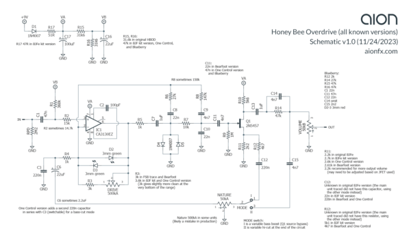
Other than simple value changes, the major structural difference is whether the Nature pot connects to the Q1 source or to lug 3 of the volume pot. Both arrangements were used in production.
We concluded the following:
- Where it connects to lug 3 of the volume pot, as on the first unit, it should be through a 4n7 capacitor, confirmed in the One Control version (which has both options switchable) as well as the Blueberry, a bass variant of the HBOD which was traced in 2015 as well as having a Moody Sounds official kit.
- Where it connects to the Q1 source, as in the second unit, it should be through a 220n capacitor, as on the Bearfoot and One Control versions, and generally through either a 4.7k or 5.1k resistor.
The Yellow Shark V2 schematic merges these two modes incorrectly, showing it connecting to the Q1 source through a 4n7 capacitor, which will have a very weak and almost inaudible treble-boost effect with Nature all the way up.
Annotated schematic
Other than that major error, there are several other minor differences between the variants. We put together an annotated schematic with the results of our research, comparing all the versions of the Honey Bee that have been traced up to this point. This schematic shows the main audio path of the circuit, omitting the bypass switching and status LED.
In each case where a part was different between versions, we included notes on which versions had which values. In most cases they don’t matter, e.g. using 47k instead of 31.6k for the bias resistors, or 14.7k instead of 15k for the input resistor. For others like C11, it would have a significant impact on the tone.
Procyon V2
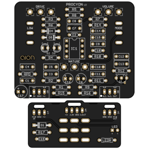 The new Procyon V2 is mostly inspired by the One Control version, which puts the two Nature connection points on a switch, with the correct capacitor values in both positions. The One Control version also adds a bass-cut mode. However, it combines this with the Nature settings under the single name of “vintage/modern”. The original Honey Bee units never had a bass cut and only ever used a 220n capacitor in the op-amp’s feedback path to ground.
This bass cut is useful, but it’s much more versatile when it’s split out as a second switch instead of forced in one mode. We split it out on our version, and also added a third mode that boosts the bass slightly, so you can either add or remove bass from the stock setting.
Notes & references
- It’s not known why it was so different, but since it was sent to this member by Bjorn himself for free, it was speculated that it was intentionally built differently from the normal units to keep the original schematic from being accurate. It seems to have worked. ↩
- The schematic is no longer hosted at FSB, but is still available from Madbean’s archives. In the YellowShark zip file, “YellowShark_ver2.pdf” is the final FSB version. ↩
